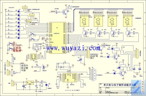
The origin of timing in microcontrollers is essential for the proper execution of instructions. As the microcontroller fetches instructions from the ROM program memory one by one, it performs a series of micro-operations to carry out specific tasks. These operations must occur in a strict temporal sequence, which defines the timing of the single-chip microcomputer. Think of it like the school bell that regulates classroom activities — everything has to be coordinated under the same signal. But how exactly is this timing defined?
Every time the computer accesses memory, it goes through a machine cycle, which serves as a time reference. In daily life, we use seconds to measure time, and similarly, a machine cycle in a computer consists of 12 oscillation cycles. The oscillation period is the time taken for one cycle of the crystal oscillator. For example, with a 12MHz crystal oscillator, the oscillation period is T = 1/f = 1/12μs. Therefore, a machine cycle would be 12 × 1/12μs = 1μs.
Inside the MCS-51 microcontroller, there's a high-gain inverting amplifier with input on pin XTAL1 and output on pin XTAL2. To create a stable self-oscillating circuit, we connect two capacitors and a crystal. While the internal workings are not detailed here, the choice of components is crucial. The crystal’s frequency determines the microcontroller’s operating speed, and the capacitor size affects the oscillator’s stability and startup time. Typically, ceramic or trimmer capacitors in the range of 10–30pF are used. It's also important to place the crystal and capacitors close to the chip to minimize PCB distributed capacitance and improve system stability.
In addition to internal clocking, the MCU can operate using an external clock signal. When multiple MCUs are involved in a system, a common external pulse signal ensures synchronization between them. If no external signal is used, the XTAL2 pin remains inactive, and the clock signal is generated internally via XTAL1.
Some instructions in the 89C51 MCU take only one machine cycle, while others require two, three, or even four. For example, the DJNZ instruction takes two machine cycles. At 12MHz, each machine cycle is 1μs, so a delay of 62500 cycles would result in 125ms. This delay is often used in experiments to control LED blinking, allowing us to observe the timing effects in real-time.
The relationship between timing and the clock is fundamental. The clock signal acts as the backbone of the timing mechanism, ensuring all operations happen in sync. Without a stable clock, the microcontroller would not function properly. The clock is generated either internally through a crystal oscillator or externally, depending on the design requirements.

Withstand high voltage up to 750V (IEC/EN standard)
UL 94V-2 or UL 94V-0 flame retardant housing
Anti-falling screws
Optional wire protection
1~12 poles, dividable as requested
Maximum wiring capacity of 10 mm2
10 amp Terminal Blocks,high quality terminal connectors,10 mm² terminal blocks,BELEKS T10 series connector strips
Jiangmen Krealux Electrical Appliances Co.,Ltd. , https://www.krealux-online.com