In order to complete a specific task, a robot must be able to perform actions. At this point, it's essential to understand how to control the robot to move straight and turn, so that it can reach the exact location where the task needs to be done.
Is moving straight really difficult for a robot?
We’ve seen advanced robots that are very stable on the road. They not only avoid obstacles but also maintain good balance even in potholes or uneven terrain.

However, there are other robots that struggle with movement, often falling due to poor balance. These robots may take steps one after another, but they lack the stability needed to stay upright.

Looking at RoboMaster’s robot games, even though these robots have four wheels, it's not easy for them to stay balanced when moving straight or performing drift turns. Proper balance control is key to smooth motion.

The red square robot demonstrates flexible positioning.
Because of control system errors, if you tell a wheel to turn five times, it might actually turn only four. Mechanical installation issues and wheel wear can also lead to differences in friction, causing the robot to drift over time.
In our previous article on PID Science, we discussed “What is PID Control in Robot Games?†The main benefit of feedback control is that by using a sensor to measure actual data, we can eliminate errors and stabilize the system to match the desired values.
Therefore, the robot must detect and correct errors in real-time to move as intended. But how do we identify those errors?
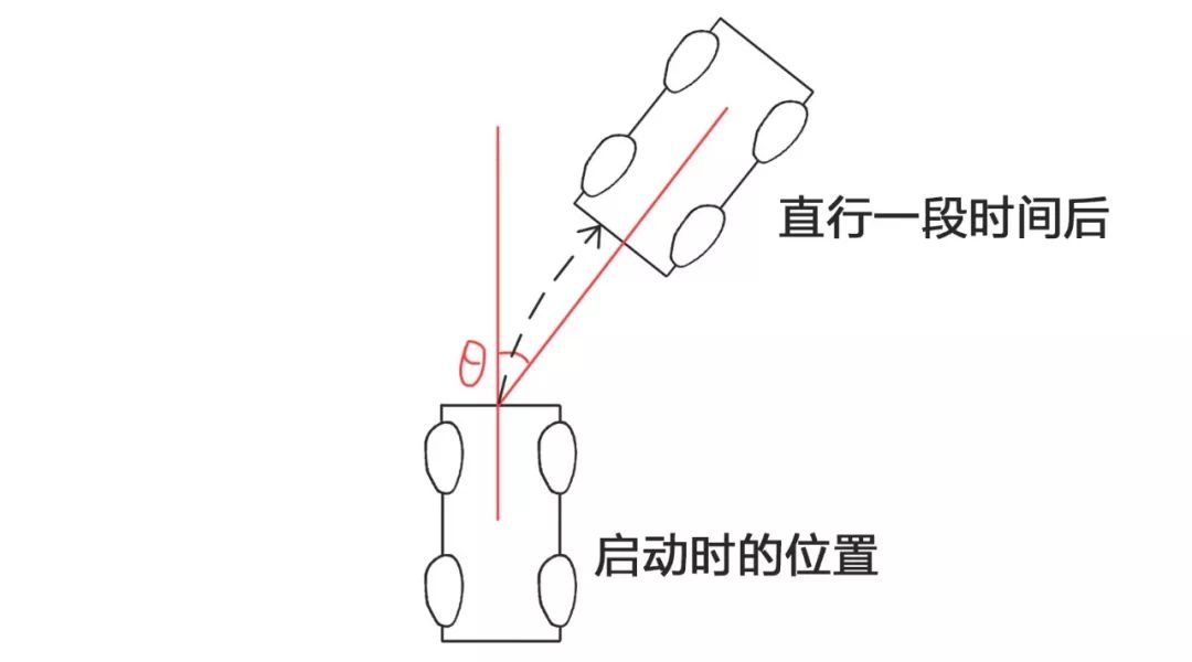
Suppose the goal is to make the robot go straight. If it starts turning left and right due to disturbances, we need a sensor to measure the rotation around the vertical axis. Then, we can use that data to counteract the unwanted movement.
Producing rotation
Finding the right sensor
Generally, selecting the right sensor involves understanding physical principles. High school physics covers forces, heat, sound, light, electricity, and magnetism. Let's start with mechanics. When an object rotates, it experiences a centripetal force F, calculated by the formula:

Although F is related to ω (angular velocity), it also depends on r (radius of rotation), which is hard to measure. So this approach isn't practical.
Another concept is the Coriolis force. When a rotating object moves linearly due to inertia, a force is generated relative to the rotating frame. Its formula is:

Here, v is a measurable vibration. Unlike centripetal force, Coriolis force doesn’t depend on radius, making it a viable option.
In reality, a sensor called a MEMS gyroscope uses this principle to measure angular velocity. After measuring angular velocity, it is integrated to get the relative angle (based on its initial state). This angle is then corrected using PID control to achieve a straight path.
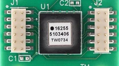
Gyro
We all know that measurements are never perfect. The angle obtained through integration is accurate for a short period, but over time, errors accumulate, making the angle less reliable. The accuracy depends on the device's cost and quality.

This same principle applies to mechanical gyroscopes and fiber optic gyroscopes. A mechanical gyroscope has a spinning top, while fiber optic gyroscopes rely on the Sagnac effect.

Mechanical gyroscope
In fact, these sensors should more accurately be called angular velocity sensors. However, for various reasons, they are commonly referred to as gyroscopes. In most applications, MEMS gyroscopes are used due to their cost-effectiveness and measurement capabilities.
Getting the rotation angle
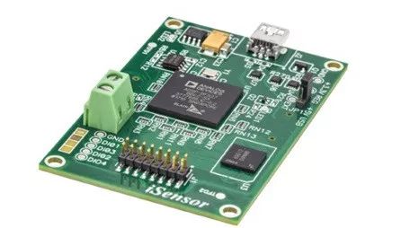
Take the ADIS16470 gyroscope as an example to explain how it measures the angle.
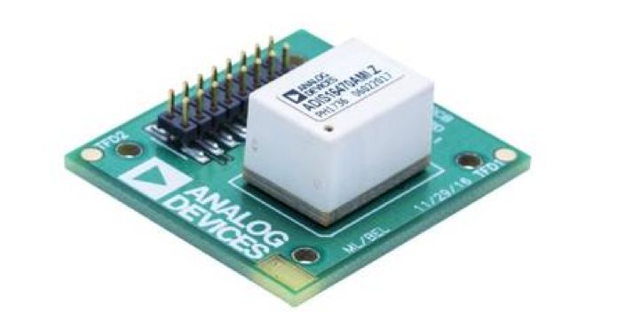
ADIS16470 gyroscope
The gyroscope measures angular velocity and integrates it to get the angle. To get a real-time angle, you need to know the time interval between each measurement and use that to re-integrate the angular velocity.
There are two ways to get the time interval:
1. Install a timer
The timer calculates the time interval and tells the gyroscope. However, there may be delays.
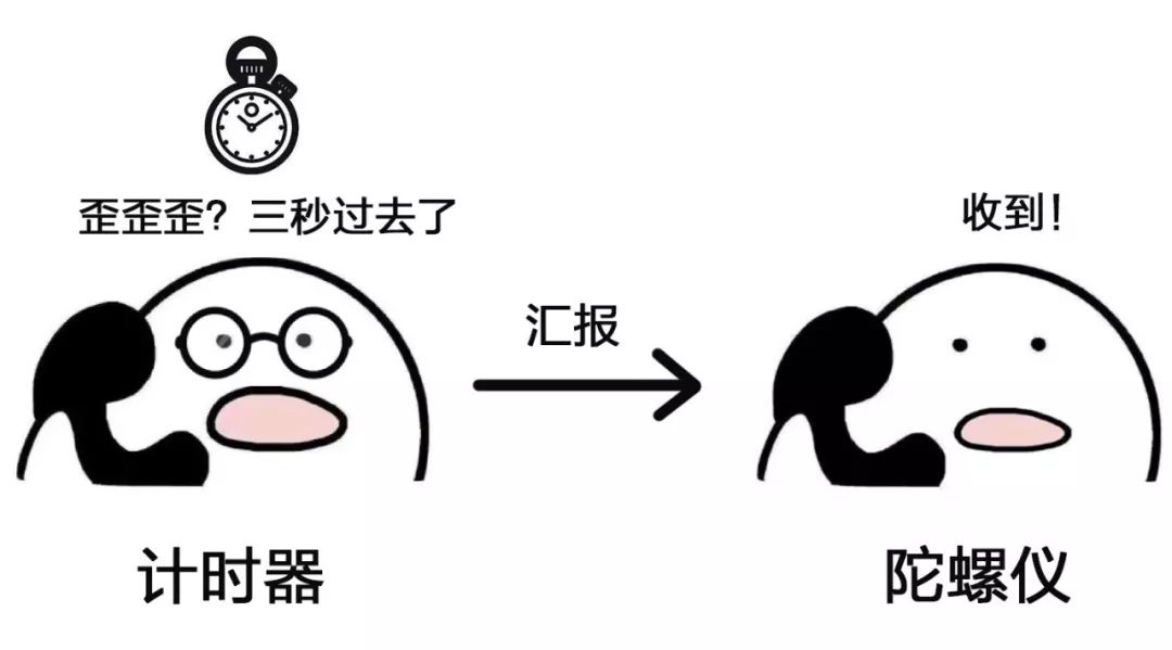
2. Gyroscope self-timing
The ADIS16470 gyroscope has its own timing function, eliminating delay errors.

Gyro error
All sensors have some error. Gyroscope errors come from external forces and temperature changes. These errors cause the robot to sway or spin slowly when stationary, a phenomenon known as drift.
Left and right jitter
While this might not matter much for ground robots, it can be critical for drones or high-precision robots, where even a small deviation can be disastrous.
How to eliminate the error
Temperature drift
Temperature-induced drift is caused by changes in internal components due to temperature. Two common solutions are:
1. Hardware-based
Add a resistor to heat the gyroscope and maintain a constant temperature.
2. Software-based
Measure temperature drift at different temperatures, then fit and compensate for it. This is called temperature calibration.
Other error sources
Besides measuring relative angles, some sensors provide absolute angles (relative to the Earth’s coordinate system). Combining these can help correct the gyroscope’s drift.
Another type of sensor is a geomagnetic meter, similar to an electronic compass that detects the Earth’s magnetic field. It provides the absolute angle, but it’s sensitive to environmental factors like motors and metal structures.
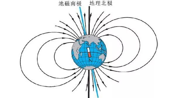
Though not always precise, it remains stable in consistent environments.
So, the gyroscope is ideal for short-term dynamic movements, but suffers from drift over time. The magnetometer works well for long-term static conditions but may be inaccurate during movement. By combining both using filtering algorithms, we can achieve a more accurate angle—this process is called attitude solution.
Data Fusion
The Kalman filter is commonly used for this. Other methods include first-order and second-order complementary filters, and adaptive parameter filters. Choosing the right algorithm depends on the application's complexity and requirements.

Kalman filter
To determine the angle, a single sensor is often not enough. Multiple sensors work together, with the gyroscope providing core data and others helping reduce drift.
In real-world engineering, attitude sensing is a common requirement. Many products now integrate multiple sensors—gyroscopes, accelerometers, compasses—into a single module, making it easier and more efficient to implement.
Multi-sensor module
Through these methods, we can determine the object’s angle relative to its starting position and use PID control to guide the robot as needed.
These sensors can also be mounted on a gimbal, allowing the chassis to move while the gimbal stays stable relative to the ground. This helps keep cameras or sensors steady, even when the robot is moving.
The gimbal stays still while the body twists
In summary, whether a robot goes straight or turns, it may seem simple, but there are many factors involved. Each step requires careful consideration. Only by choosing the right sensors can we effectively solve the problem and ensure smooth, accurate robot movement.
Outdoor Bluetooth Speaker,Sound Equipment,Active Pa Speaker,Professional Speaker
NINGBO RFUN AUDIO TECHNOLOGY CO.,LTD , https://www.mosensound.com