Application of Industrial-Grade High-Precision 3D Scanners in the Detection of Casting Sizes for New Product Development
A high-precision 3D scanner is used to capture detailed data of a product, creating a point cloud that is then transferred to a computer for further analysis. During the scanning process, various device settings can be adjusted to enhance accuracy, and the more precise the scan, the denser the point cloud becomes. This digital data is then used to construct a 3D model, which is compared with the original design model. The process is illustrated below:
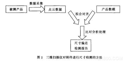
Once the model number matches the product number, a comparison between 3D and 2D dimensions is conducted. The 3D dimension check includes color deviation mapping, 3D measurements, and geometric tolerance evaluation. For 2D comparisons, any section of the product can be selected to measure feature distances, radii, and angles.
After completing all necessary 3D dimensional inspections and annotations, a detailed inspection report can be generated. If multiple identical products are being tested, the previous test can be used as a template. Simply replace the original scan data with new data and run an automated report to produce an updated test result.
The use of high-precision 3D scanners has become essential in detecting casting sizes during the development of new products. Traditional methods such as manual scribing are limited in their ability to measure complex or curved surfaces. With the increasing reliance on 3D data, traditional 2D drawings are no longer sufficient. As a result, 3D scanning offers a more efficient and accurate solution for quality control.
1) Casting Inspection
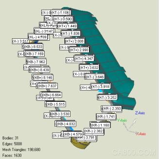
The scanned data of the casting is imported into analysis software alongside the 3D model. Alignment is typically done using reference points and features. First, the horizontal machining positioning point is used as a reference for fitting, followed by automatic alignment. The choice of alignment method depends on the specific product. It's best to use the primary machining reference point whenever possible. The principle is shown in the figure below:
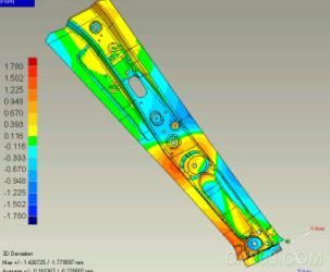
After alignment, a 3D comparison is performed to generate a color deviation map. This visual representation helps technicians quickly identify dimensional discrepancies on the casting surface. For specific areas requiring detailed measurement, comments can be added to display exact deviation values. This is especially useful when checking whether there is enough material left for machining or verifying flatness through geometric tolerances. Large deviations can also be annotated for further review. By analyzing these annotations, patterns in dimensional changes can be identified.
Key dimensions like the cylinder bore diameter and center-to-center distance between cylinders can be easily measured using feature creation and 3D dimensioning tools.
2) Sand Core Inspection
In the development of new castings, sand cores may deform over time due to wear or other factors. Measuring these cores was previously challenging, making it difficult to track their size accurately. With 3D scanning, non-contact measurement becomes straightforward, allowing for quick and reliable core size assessments.
During rapid trial production, many sand cores are produced without molds, leading to inconsistent sizes. Multiple tests are required to determine the actual dimensions. Based on the results, adjustments can be made if certain parts exceed the acceptable range.
The application of industrial-grade 3D scanners in casting size detection has proven to be a powerful tool in modern product development, improving efficiency, accuracy, and overall quality control.
Wuxi Motian Signage Co., Ltd , https://www.makesignage.com