Smart car is a comprehensive system that integrates environmental awareness, planning decision, and automatic driving. It can adapt to different environments, is not affected by conditions such as temperature and humidity, and completes tasks in special situations such as dangerous areas and humans' inability to intervene. Therefore, it has extremely important applications in military, aviation, and expedition fields. However, with the deepening of the application, in many occasions, multiple cars need to be able to communicate in real time and work collaboratively. Based on the above considerations, this paper developed a smart car with wireless communication function based on STC89C52 and nRF24L01. The car not only has functions such as tracking and obstacle avoidance, but also can communicate wirelessly in real time within a certain distance and cooperate to carry out related work.
1 system design 1.1 system overall designThe smart car design based on STC89C52 and nRF24L01 involves sensor application, wireless data transmission, etc. The overall scheme of the system is shown in Figure 1.
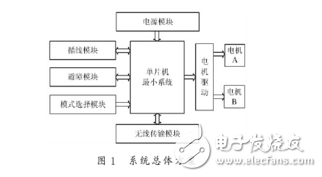
The whole system consists of the MCU minimum control system, power module, motor and drive, wireless communication module, mode selection module, tracking module and obstacle avoidance module. After the smart car is powered on, the mode selection module can be used to determine the working mode of the car (as a master or slave, tracking or obstacle avoidance, etc.); the tracking and obstacle avoidance module performs corresponding actions according to the data detected by the corresponding sensor. In order to enable multiple cars to coordinate work at the same time, it is necessary to obtain the precise positioning of the other party. Here, the coordinate system can be established and the coordinates can be updated in real time according to the operation situation, and the communication between the cars can be realized by designing the communication module and the corresponding communication mode.
1.2 feature signal selectionIn order to achieve automatic driving, the sensing system of the smart car must acquire two kinds of characteristic signals of the state characteristics of the car and the characteristics of the road environment through various sensors.
1.2.1 trolley characteristic parameters
When the car works together, it needs to know the position and driving mode of the other party, so that the coordinates of the information collection point can be obtained. The feature status includes the following parameters:
Travel mode, the travel mode determined by the DIP switch.
Cart coordinates, the coordinates of the current position of the cart relative to the location of the power-on.
The program flag bit indicates whether the data has received the data.
Direction, the angle between the current state of the cart and the x-axis direction. When the power is turned on, the front of the vehicle body is in the x-axis direction, and the counterclockwise rotation is 90° in the y-axis direction. The unit pulse rotation angle, the microcontroller outputs the angle of the unit pulse car, and the data needs to be measured.
The unit pulse displacement, the microcontroller output unit pulse car changes the displacement, the data needs to be measured. The number of pulses, the number of pulses output by the microcontroller during the movement of the trolley.
1.2.2 Environmental characteristics parameters
In actual work, the two vehicles need to know the state of the other party, so the wireless transmission data should include environmental characteristics parameters. The environmental status includes the following parameters:
Status bit, the status flag of the flag is detected during the running of the trolley.
Road status, the state of the road read by the laser sensor.
Obstacle state, the state of the obstacle read by the photosensor. Absolute displacement, the relative position between the two cars.
1.2.3 Parameter definition and calculation
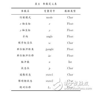
See Table 1 for the definition of each parameter in the program.
The formula for calculating the direction of the cart is as shown in equation (1):
Angle=angle±n*Δangle(1)
The formula for calculating the coordinates is as shown in equation (2) and equation (3):
x=x+cosα*n*Δs(2)
y=y+sinα*n*Δs(3)
The formula for calculating the absolute displacement is as shown in equation (4): L0=(x 1-x2)2+(y1-y2)2(4)
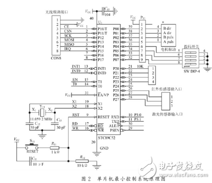
2 system hardware implementation 2.1 single-chip minimum control systemThe schematic diagram of the minimum control system of the MCU is shown in Figure 2. The system uses the STC89C52 MCU as the control core, and the microcontroller is connected to each module through the I/O port.
The STC89C5 is a low power, high performance CMOS 8-bit microcontroller with 8K in-system programmable FLASH memory. It has the following standard functions: 8KB FLASH, 512BRAM, 32bI/O line, watchdog timer, built-in 4KB E2PROM, MAX810 reset circuit, three 16-bit timer/counters, one 6-vector 2-level interrupt structure, full duplex Serial port. The design of the sensor requires a total of 20 controller I / O ports (6 sensors, 4 motors, 6 wireless modules, 4 DIP switches), the output processing speed is not high, the I / O of the STC89C52 chip Ports, interrupts and timers can fully meet their functional requirements.
2.2 motor driveSince the output current of the single chip cannot directly drive the motor, the system uses a stepping motor driven based on the TB6560 chip to drive the stepping motor.
TB6560 is a low-power, high-integration two-phase hybrid stepping motor driver chip from Toshiba. Its main features are: internal integrated dual full-bridge MOSFET drive; maximum withstand voltage 40V, single-phase output maximum current 3.5A (peak); with full step, 1/2, 1/8, 1/16 subdivision; built-in temperature protection Chip; with overcurrent protection; packaged in HZIP25.
The TB6560-based drive circuit has three control signals for the stepper motor (CLK, CW, ENABLE). The direction of the motor is controlled by the P0.0 and P0.1 terminals of the microcontroller respectively. When the output level type is the same), P0.2, P0.3 control the speed of the motor. The enable terminal in this circuit is always connected to +5V.
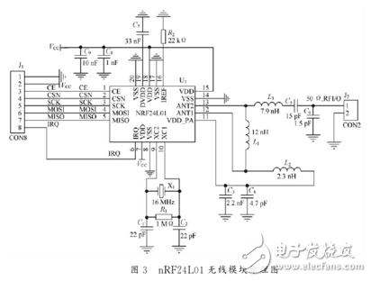
2.3 communication moduleThe wireless communication module of this system uses the nRF24L01 wireless module. The nRF24L01 is a new single-chip RF transceiver with built-in frequency synthesizer, power amplifier, crystal oscillator, modulator and other functional modules combined with enhanced ShockBurst technology. It operates in the 2.4 to 2.5 GHz ISM band, where the output power and communication channel can be configured through the program. The nRF24L01 has low power consumption. When transmitting at -6dBm, the operating current is only 9mA. When receiving, the operating current is only 12.3mA. A variety of low-power operating modes (power-down mode and idle mode) make energy-saving design more convenient.
After the mode selection module determines the master and slave modes of the car, the host sends the data after detecting the corresponding mark line, and the slave responds and feeds back its own information after receiving the data, and executes the corresponding program.
The schematic diagram of the nRF24L01 wireless module is shown in Figure 3. The CE pin function is to enable transmission or reception, controlled by P1.0; CSN, SCK, MOSI, MISO are SPI pin terminals, and the microprocessor can pass P1.1. P1.2, P1.3, P1.4 to configure nRF24L01; IRQ is the interrupt flag, controlled by P1.5.
The tracking module uses three laser sensors, model HLSD-2010B, placed in the left, right, and front of the car, controlled by P2.5, P2.6, and P2.7.
The HLSD-2010B laser sensor has an operating voltage of 5V, an operating current of up to 30mA, and a signal output mode for direct level output.
The laser sensor truth table is shown in Table 2. The controller performs different actions for different measured values.
2.5 obstacle avoidance moduleThe obstacle avoidance module uses four photoelectric sensors, and the model number E18-D80NK is placed in front of the vehicle body.

The technical parameters of photoelectric sensor E18 are 5V, the current consumption DC is less than 25mA, the response time is less than 2ms, the pointing angle is less than or equal to 15°, the effective distance is adjustable from 3 to 80cm, and the working environment temperature is -25 to 55°C.
According to different environments, the smart car obstacle avoidance movement can be divided into four situations, as shown in Figure 4.
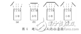
(1) Only the infrared sensors of No.1 and No.2 detect obstacles. At this time, the trolley moves to the right. If the sensors No.3 and No.4 detect it, they move to the left direction.
(2) When the current party finds an obstacle, and the obstacles that are not detected on the 1st and 4th, the car moves to the right.
(3) When four infrared sensors measure obstacles, the car first goes backwards and then moves to the right.
(4) If 1, 4 detects an obstacle and 1, 3 does not detect an obstacle, the car does not change direction and still walks in a straight line.
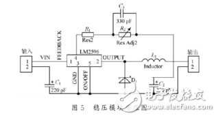
2.6 power moduleThe system is powered by two lithium batteries with a capacity of 2 250 mA·h and a rated voltage of 3.6V. Since the operating voltage of the MCU, tracking module and obstacle avoidance module in the system is 5V, the working voltage of the wireless module is 3.3V. Two DC-DC voltage regulator modules composed of LM2596 chip are used in the design process.
The schematic is shown in Figure 5. For the microcontroller regulator module, the input is 7.2V and the output is 5.0V. For the nRF24L01 regulator module, the input is 5.0V and the output is 3.3V.
ZGAR PCC
ZGAR electronic cigarette uses high-tech R&D, food grade disposable pod device and high-quality raw material. All package designs are Original IP. Our designer team is from Hong Kong. We have very high requirements for product quality, flavors taste and packaging design. The E-liquid is imported, materials are food grade, and assembly plant is medical-grade dust-free workshops.
From production to packaging, the whole system of tracking, efficient and orderly process, achieving daily efficient output. We pay attention to the details of each process control. The first class dust-free production workshop has passed the GMP food and drug production standard certification, ensuring quality and safety. We choose the products with a traceability system, which can not only effectively track and trace all kinds of data, but also ensure good product quality.
We offer best price, high quality Vape Device, E-Cigarette Vape Pen, Disposable Device Vape,Vape Pen Atomizer, Electronic cigarette to all over the world.
Much Better Vaping Experience!


E-Cigarette Vape Pen,Disposable Device Vape,Vape Pen Atomizer,Latest Disposable E-Cigarette OEM vape pen,OEM electronic cigarette
ZGAR INTERNATIONAL TRADING CO., LTD. , https://www.zgarvape.com