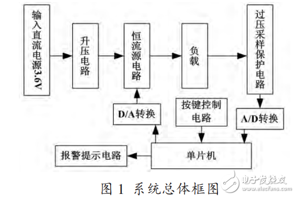
The system is converted by an input DC power supply through a switching type booster circuit, and outputs a voltage of 12V to provide a working voltage for the constant current source circuit. The D/A output signal inside the MCU is controlled by a button to make the constant current source circuit output a constant current. At this time, when the voltage value at both ends of the load is greater than the set value, the alarm module is controlled by the internal A/D signal of the MCU. The system structure block diagram is shown in Figure 1:
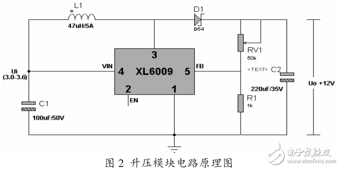
The circuit is mainly composed of XL6009 step-up DC power converter chip, Schottky diode B54 and inductor. The 3-pin output of the XL6009 is a square wave signal. As a switch, when the 3 pin outputs a low level, D1 is cut off, the inductor L1 acts as a storage element to store the voltage, and the capacitor and RV1 and R1 form a loop discharge, causing the output voltage to drop; when the 3 pin outputs a high level, D1 is turned on, Inductor L1 charges both ends of the capacitor and the output voltage rises. RV1 and R1 are voltage amplifiers with internal XL6009. As a negative feedback, the output voltage is regulated by a resistor RV1 and R1. The schematic diagram of the boost module circuit is shown in Figure 2:
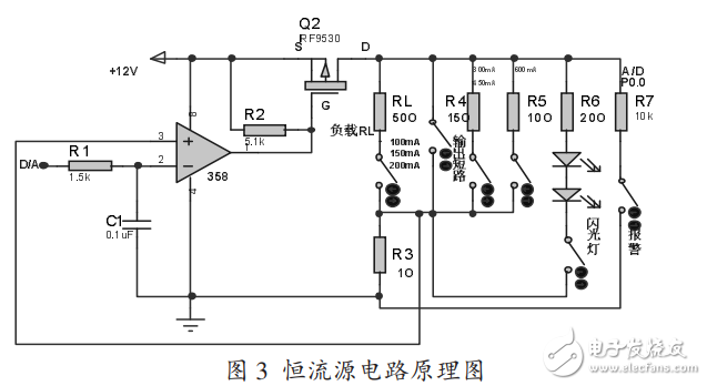
The circuit is mainly composed of LM358 op amp and P-channel FET F9530N. When the D/A output voltage (ie, the 2-pin voltage) rises, the output voltage of pin 1 of LM358 decreases, the voltage of gate G and source S of F9530N increases, and the voltage between SD controls decreases, so that the load and ground are reduced. As the voltage increases, the sampling voltage increases, causing the voltage of pin 3 of the LM358 to follow the voltage change of the 2 pin, thereby acting as a constant current. Through the switch on and off, switch different loads, so that the output current meets the requirements of constant current of different gears. The principle of the constant current source circuit is shown in Figure 3.
The input voltage is 3.0~3.6V, so choose a lithium battery with a rated output voltage of Uout=3.6V. According to the maximum output power is Pmax=10V*0.6A=6W, calculated according to the system efficiency of 80%, the output power of the input power supply Pout=Pmax/0.8=7.5W, the output current of the input voltage I=Pout/Uout=2.08 A. The maximum output current of a dry battery is 2.2A. To ensure the freewheeling capability, two 3.6V lithium batteries are selected.
5. Ways to improve efficiency(1) F9530N is a low-dropout FET. It belongs to a voltage-controlled device. Its conduction will consume almost no current and the power consumption is extremely small. Therefore, F9530N is chosen to improve efficiency.
(2) The resistance of the sampling resistor is small and the power consumption is relatively small.
(3) The wiring of the power supply is made of thick copper wire, the internal resistance is very small, the corresponding loss is small, and the output power is increased, so the efficiency is improved.
6, system test results and analysisWhen connected to the load, the corresponding output voltage, output current and relative error are shown in Table 1 in continuous output mode:
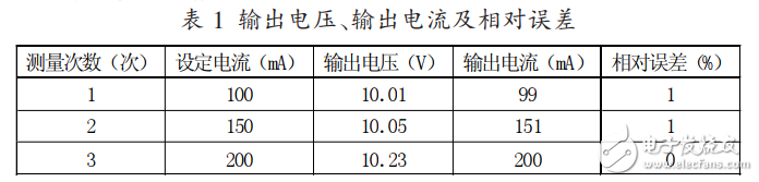
As can be seen from Table 1, when the load is connected, the output current can be set to 3 steps in the continuous output mode. The maximum output voltage is 10.23V, and the maximum output current relative error is 1%. The LED flash can work normally, with precise control, small error, and high-precision real-time display of voltage and current.
Nintendo WII U Console Adapter
This WII Uadapter is factory supply with cheap price and high quality, we provide US EU UK Plug, for the UK plug, we also can do fused plug to protect your charger better.
- ✅Parameter: Input: 100V-240V: Output: 15V 5A; Cable Length: 7 feet.
- ✅High Quality: Made from durable material for long time use, and with auto voltage feature that allows the adapter to be used worldwide.
- ✅Specially Made for Nintendo Wii U GamePad. Ideal quality replacement or backup power AC adapter for your Wii U GamePad.
- ✅Simple plug and play setup, With overheating, overcurrent, overcharge protection.
- ✅Package Included: 1 x AC Power Adapter for Nintendo Wii U GamePad. 100% Satisfaction Guaranteed Warranty.12-Month Manufacturer`s Warranty.
➤ Top quality replacement power adapter for Nintendo Wii U Console(With automatic voltage function)
➤Output: 15V 5A;Simple plug and play setup, allow you to charge and play at the same time from up to 7 ft away.
➤ It supports to use both AC 110V and AC 220V, which avoids the defect of using AC 110V only with original Nintendo adapter.
Product Specifications:
- Color: Grey
- Input: AC 100-240V
- Output: DC 15V5A


- Cable Length: Approximate 90cm (Wall plug side to AC adapter), Approximate 100cm (Console side to AC adapter)
Nintendo WII U Adapter, Nintendo WII U Console Charger, Nintendo WII U Adaptor, Nintendo WIIU AC Charger, Nintendo WII U Power Supply
Shenzhen GEME electronics Co,.Ltd , https://www.gemesz.com