Summary
This article discusses the application of GPS global positioning technology in medical monitoring, and prepares a GPS medical monitoring positioning device, which is mainly composed of two parts: a single-chip microcomputer control module and a GPS receiving module. The advantage of low power consumption realizes the need for outdoor care.
1 Introduction
At present, there are about 300 million care groups in China, mainly children and elderly patients. As the rhythm of modern life is tense, parents are busy with work, children have more free space to move, and children are often found to be lost and injured; patients in hospitals, such as patients with dementia, also have a phenomenon of loss. How to realize the supervision of this group at any time has become a problem that the caregivers are very concerned about and eagerly hope to solve.
GPS (Global Positioning System) [1] was developed by the United States in the 1970s. It lasted 20 years and cost 20 billion US dollars. It was fully completed in 1994 and has full-time real-time 3D navigation and positioning capabilities in sea, land and air The satellite system has the characteristics of good performance, high precision and wide application. It has been opened for free and is the best navigation and positioning system to date. With the continuous improvement of the global positioning system, the continuous improvement of hardware and software, the application field is constantly expanding. At present, it has spread to various sectors of the national economy and has gradually penetrated into people's daily life. We use GPS technology to prepare the positioning device for monitoring to meet the real-time care of the family to the child and the hospital to the patient, so that parents at work can rest assured, prevent the loss of the hospital patient, improve the level of hospital care for the patient, expand the patient Range of activities.
2. Device hardware design and implementation
The medical monitoring device (Figure 1) is composed of two major parts: a single-chip microcomputer control module and a GPS receiving module. The two modules exchange information through a serial port mechanism. .
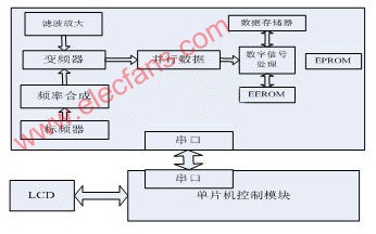
Figure 1 System structure of medical monitoring device
2.1 SCM control module (Figure 2):
Through the expansion of the peripheral circuit, the acquisition of physiological parameter data, keyboard operation, LCD display of physiological parameters and automatic alarm are realized. For LCD, we use G191 liquid crystal module, 192 & TImes; 128 dot matrix, dot size is 0.33 & TImes; 0.33mm, dot pitch is 0.04mm, drive power is + 5V and -20V. We use SED1335 for the LCD controller. The controller is used to receive various commands and data from the control module and generate corresponding timing to control and display the LCD screen. The software function of SED1335 is very powerful, and it comes with data RAM and can be managed by itself Display the cache area for our convenience.
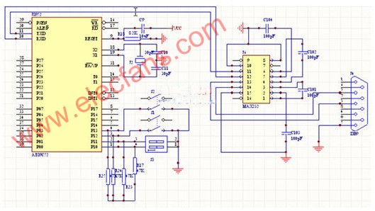
Figure 2 SCM control module circuit
2.2 GPS receiving module:
Responsible for receiving information from GPS satellites (space part) and sending data to the microcontroller control module through the UART serial port in real time. In the design process, through analysis and comparison, we selected the GR-85 serial GPS receiver of Taiwan HOLUX company. In terms of signal capture and signal accuracy, GR-85 has its unique advantages. The signal recapture time only needs 100ms, and the minimum speed update rate can reach 1s.
The GR-85 receiving module adopts serial communication, and its data format is defined as follows: 9600b / s, 8 data bits, 1 stop bit, and non-polarity output. GR-85 supports six types of NMEA-0183 protocol information: GGA, GLL, GSA, GSV, RMC, VTG. The difference between these six types of information lies in the type of information that users can receive. For example, there is speed information in RMC format, but not in other formats. The designer can choose the format of the response information according to his needs. This experiment uses the RMC format. Table 1 shows the pins of the GPS receiver module. The communication between the receiving module and the single chip microcomputer mainly passes through the TXA pin.
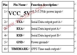
Table 1 GPS receiving module pins
3. System software design and implementation
As long as the GPS receiving board is in the working state of power-on, it will continuously transmit the GPS navigation and positioning information received and calculated to the single-chip microcomputer system through the serial port. The extraction of GPS information must first clarify its frame structure. The data frame is mainly composed of frame header, frame tail and intra-frame data. Carriage returns
In order to store the received and processed time and its longitude and latitude data, we have drawn a fixed space in the memory. Among them, 3BH-5FH is used to store the received time, longitude and latitude data, and 6BH-7FH is used to store the processed time, longitude and latitude data.
The system flow chart is shown in Figure 3:
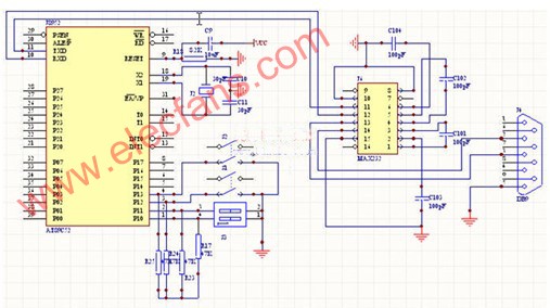
Figure 3 System flow chart
3.1 GPS data output format is as follows:
$ GPRMC, <1>, <2>, <3>, <4>, <5>, <6>, <7>, <8>, <9>, <10>, <11> * hh
The format is described as follows: <1> Greenwich time at the current location, the format is hhmmss; <2> status, A is a valid location, V is an ineffective receiving warning, that is, the number of satellites above the current antenna field of view is less than 3; <3 > Latitude, the format is ddmm.mmmm; <4> indicates the northern and southern hemispheres, N is the northern hemisphere, S is the southern hemisphere; <5> Longitude, the format is dddmm.mmmm; <6> indicates the eastern and western hemispheres, E is the eastern hemisphere, W is the western hemisphere; <7> Moving speed of the GPS receiver on the ground; <8> Azimuth, range is 000.0 ~ 359.9; <9> Date, format is ddmmyy; <10> Geomagnetic change; <11> Geomagnetic change direction, E or W.
Sample output: $ GPRMC, 161229.487, A, 3723.2475, N, 12158.3416, W, 0.13,309.62,120598,, * 10
12V UPS Charger, Restorer and Tester 3-in-1 Recovery system , is fit for 12V/36 Ah~300Ah lead-acid battery banks, With digital pulse charger, adjustable restorer and adjustable discharge Tester, high-performance of recover battery, convenient and reliable. Mainly used in the UPS industry of Wind and Solar energy storage battery, UPS Back up power system, Telecom base site battery , State Grid and Military battery for sudden affair, etc. It has been selected as a approval item of Chinese military cooperation products list, and as an important part of the military emergency combat system, as well as reducing a large number of military batteries back up power purchase cost than before.
This 3-in-1 integrated Recovery system is composed of 3 parts and a professional standard restore process: 1) 12V Battery Restorer Device(36~300Ah); 2) 12V Battery Digital Pulse Charger; 3) 12V Battery Discharge Tester. It is applicable to all of Lead Acid UPS Battery(AGM, GEL, VRLA, Flooded, Dry, Deep cycle and Stationary), and widely used in 12V (36~300Ah) cell batteries.
1) Digital pulse charger
4 Pulse charge channels , each channel have three ranges :10A, 15A, 20A , Select the right charging current according to the capacity and conditions of batteries , the system have a special IC to control automatically recharging without on duty. The multiple-stage pulse charger has the function of preventing battery dehydrated, preventing overcharged, and protect battery plate with equalized pulse charging function.2) Non-destructive Smart Pulse Restorer
8 Pulse restore channels for different capacity of batteries: 36Ah~75Ah, 75Ah~120Ah, 100Ah~300Ah. Selecting the suitable range can be ensure better protection of battery plate in restore working, and extend batteries life up to 2 times than before. It is also called Battery Pulse Desulfurizer, Battery Refresher or Sulfuric Crystal Cleaner and maintainer
3) Discharge Capacity Tester
4 discharge channels of detecting and capacity testing , with discharge current range: 0A~ 20A(Output discharge current can be adjusted continuously and input power accurately.), current precision: ±1% and voltage error: 0.05V. Choose the right ranges of discharge current in order to improve the efficiency of battery recovery, Prevent deep discharge and make sure the plates to be protected better.
12V UPS Charger Restorer Tester 3-in-1
12V UPS Charger Restorer Tester 3-in-1,UPS Battery Saver,12V UPS Charger Restorer Tester,UPS Battery Smart Charger and Tester
Shenzhen Daceen Technology Co., Ltd. , https://www.daceen-sz.com