Modulation reference signal can search the maximum value of phase detection
1 Introduction
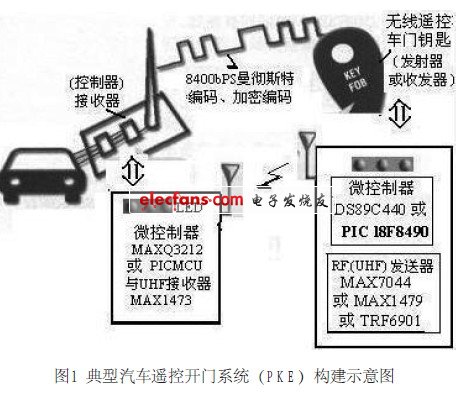
This article will analyze and introduce the new design scheme and application development of the car wireless remote control door opening system. The typical wireless remote control door opening system-remote key (RKE) system used in automotive safety applications is shown in Figure 1. The system consists of a controller (or receiver) installed on the car and a transceiver (or transmitter) carried by the user, that is, a wireless remote control door key. The transceiver generally includes a microcontroller, RF device, and human-machine interface devices such as buttons and LEDs. The microcontroller can use DS89C440 or PIC16F639, and the RF device can use MAX7044 or MAX1479 or TRF6901. The transceiver is usually turned off and only works when the button is pressed or data needs to be sent. The transceiver is used to send data to the controller, so it is a one-way communication. However, this situation is changing. The new smart transceiver can send and receive data, so it is a two-way communication. In a two-way communication system, the controller (installed on the car) and the transceiver (that is, the car key) can achieve automatic communication without the need for a human-machine interface.
2 Design ideas
It can be seen from the composition of the above-mentioned wireless remote control door opening system that the design idea of ​​the system scheme is based on the construction of a transmitter (remote key) and a receiver with a microcontroller.
As we all know, the MAXQ series is a 16-bit RISC microcontroller that uses a low-noise design and is optimized to work with analog circuits. It can be integrated with RF receiver devices to build the best solution for analog circuits.
2.1 Remote key (transmitter or transceiver) and receiver (vehicle controller)
The remote control key can use DS89C450-KIT and MAX7044 or two evaluation boards (EV KIT), namely DS89C450-KIT and MAX7044EVKIT (EVht) to form the transmitter. It can be installed in a housing with the rechargeable battery below. If an antenna is used, the transmission distance exceeds the standard key chain by several orders of magnitude.
The receiver (vehicle controller) can be composed of a MAXQ3212 16-bit microcontroller and a MAXl473 receiver installed side by side. The connection is connected to the body control module (BCM) of the car. If you are doing debugging or demonstration, you can use a dedicated MAXQ3212 port pin to send asynchronous serial data at 9600bps.
The reason why the MAXQ3212 16-bit microcontroller is used here is because the MAXQ series is a low-noise design and is optimized for working with analog circuits. The 16-bit RISC microcontroller is integrated with high-precision analog in addition to digital components. Function, so the number of chips required for the application program is less, can be integrated with the RF receiver device MAXl473 to build the best solution for the analog circuit, and basically does not interfere with the RF signal. Its excellent power consumption characteristics and powerful function combination make the design and construction of products easier, and can shorten the time to market.
The RF receiver device MAXl473 is the latest 300MHz to 450MHz ASK (amplitude conversion modulation) RF receiver. The average sensitivity is -114dBm, and normal operation consumes only 5.5mA (typical) current. Built-in image frequency suppression eliminates the need for commonly used front-end SAW filters. In sleep mode, MAXl473 can start and send data in less than 250ps, ensuring a deeper sleep cycle and longer battery life. MAXl473 can work at a supply voltage of 3V to 5V. The biggest advantage of the 300MHz to 450MHz transmitter and receiver is that it can double the effective distance of the RKE system, and can be ideally applied to sub-battery-powered equipment, including keys, car alarms and tire pressure detection.
2.2 About analog signal strength measurement
The MAXl473 receiver provides an analog received signal strength indicator (RSSl) that can measure this signal. The MAXQ3212 includes an analog comparator to compare the VREF and CMPI inputs, and can generate a pulse-width modulation signal (PWM) on the timer output pin. Fig. 2 shows the method of constructing ADC by comparator and PWM. Send the RSSI signal to the VREF pin of the MAXQ3212 comparator. Then program the timer into PWM mode. If the PWM is properly filtered, the DAC output can be generated to the T2PB pin, and the output (ie, DAC) can be connected to the other input CMPI pin of the comparator. The comparator then compares the signal levels, and if the signals match, it can successfully perform analog-to-digital conversion without a dedicated hardware ADC.
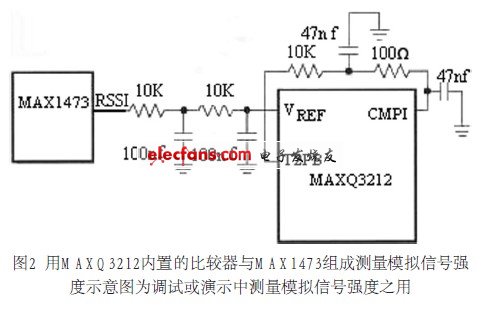
The successive approximation method is not used in the software, but the slope ADC is used. Starting from a reasonable minimum, the DAC output slowly increases until the comparator indicates a matching state.
2.3 How to decode the RF signal
The MAXl473 receiver provides a digital signal output (DATAOUT). Since RF noise is always present, this pin will continuously change state regardless of whether the keychain is actually sending data. To distinguish this noise from the signal, the MAXQ microcontroller must use a small software state machine that measures the time between the rising and falling edge signals to identify the preamble.
The most effective way to measure the edge interval is to use interrupt triggering technology. MAXQ can be programmed to trigger an interrupt on a rising or falling edge. Set the interrupt to the "rising edge" trigger and the measurement will start. Once a rising edge is detected, the timer is reset and restarted, and the interrupt trigger edge is set to the "falling" edge. At the falling edge, the interrupt handler reads the value of the timer. This can be a small piece of program to show a code segment, which reads and resets the timer, and then switches the polarity of the interrupt trigger signal. If the edge interval matches the 8400bps data rate (plus / minus a reasonable tolerance) and the number of sync pulses specified in the protocol is detected, the microcontroller software state machine switches to receive mode and begins parsing the remaining packets.
2.4 About the data stream-the use of Manchester encoding
The protocol of the transmitter (remote key) data stream (burst) shown in Figure 1 varies greatly due to the manufacturer, model, and time of shipment. For this aftermarket project, the use of programmable microcontrollers is just right. Here, the digital data stream of 8400bps Manchester encoding is randomly selected, and the ASK (Amplitude Conversion Modulation) method is used to transmit at 433MHz. If you want to use FSK (frequency conversion modulation) or different transmit frequencies, you must replace MAXl473 with a different receiver chip.
(1) Basic concepts of Manchester encoding
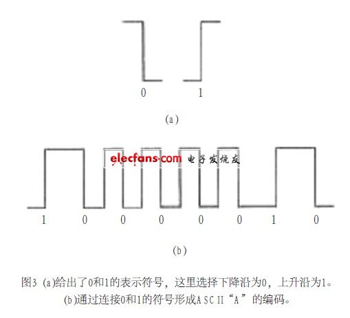
Each data bit is represented by at least one signal transition to achieve self-synchronization of the data stream. Figure 3 (a) gives the symbols for 0 and 1, where the falling edge is selected as 0 and the rising edge is 1. Serial data is usually sent LSB first. As shown in Figure 3 (b), the ASCII character "A" (41h, 0100.000lb) is sent in the form of 1000.0010b. The code can be formed by connecting 0 and 1 symbols. Figure 3 (b) forms the ASCII "A" code by connecting 0 and 1 symbols.
(2) Data flow and software
When the button on the key chain is pressed, the preamble will be sent, followed by the ID, count value, and key data, as shown in Figure 4. Before the button is released, the transmitter repeats this sequence process, and a software debounce procedure is also required. In this example code, it is simply achieved by briefly turning off the receiver.
The actual system will also encrypt part of the data to prevent the vehicle from being stolen. It is generally decrypted by the car body control module (BCM). The receiver software measures the received signal strength, waits and synchronizes to the preamble, decodes the data stream and transmits the data through the serial port.
Aluminum Profiles Materials and features:
1, the shape led jewelry counter lamp housing are V-shaped, U-shaped and triangle, so the jewelry counters led lamp housing, also known as V-groove, U-groove and triangular-shaped groove;
2, Sichuan and spread of new energy production can be equipped with plug, 90 degree angle, angle of 135 degrees, 180 degrees straight through led jewelry counter lamp housing, 6063 GB of raw materials are all aluminum, high purity aluminum, quality assurance, all through the testing and certification;
3, surface gloss, uniform oxide film, bright color, color uniformity, corrosion resistance;
4, the appearance of fine, beautiful, overall product design scientific and rational, durable;
5, high-pressure tensile aluminum shell, good heat dissipation, and diverse styles.
6, product variety, can be customized according to customer demand.
7, the surface may be anodized, electrostatic spraying, gloss treatment
8, streamlined design, the appearance of multilateral tooth design, increase the cooling area, cooling fast.
Aluminum Profiles
Aluminium Profiles,Aluminum Profile For Curtain Wall,Aluminium Profiles For Windows And Doors,Waterproof Aluminium Profiles
Shenzhen Mingxue Optoelectronics CO.,Ltd , https://www.led-lamp-china.com