1 Introduction
As a high-precision measuring instrument, the CMM is widely used in the machinery industry, automobile industry, aerospace and other fields. This set of communication system adopts FPGA as the main communication chip, uses FPGA to realize the transmission and reception of data by each communication module, and cooperates with the single chip to encode, decode, and repackage the data to realize the communication between the computer and the control system; due to the parallel execution structure of the FPGA program And high execution speed, thus greatly ensuring the accuracy and speed of data transmission.
2. Realization of communication module
2.1 Communication between computer and bridge card
This system uses RS232 bus to realize the communication between the computer and the bridge card. The data sent by the computer is transmitted to the bridge card via the RS232 bus, and the level conversion is realized through the MAX3232 chip. The FPGA receives the data after detecting the start bit and stores it in the UART receive FIFO [2] after receiving the data; when the end bit is received, the FPGA generates an interrupt signal that triggers the microcontroller to read the data in the receive FIFO and It decodes, judges the destination address in the data, and decides whether to process or send it to the control board according to the destination address; when the bridge card communicates with the computer, the data is first encoded, and then the data is placed in the transmission FIFO, the transmission module is started, the transmission module The data is sent out automatically, and the data is sent to the bus via MAX3232 to wait for the computer to receive it.
(1) FPGA implementation of serial port sending module
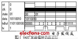
After the serial port sending module reads the data from the transmit FIFO, according to the serial port communication protocol, when the data is sent out, the low bit is in the front and the high bit is in the back, so the eight-bit data is re-edited: add the stop bit '1' before, Add the start bit '0' to become a ten-bit data packet, and send the ten-bit data bit by bit according to the set baud rate. Use Modelsim for simulation. The simulation diagram is shown in Figure 1 (data to be sent by the data bit, tx is Send line)
(2) FPGA implementation of serial port receiving module
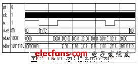
When the bus is idle, when the change from high to low is detected, it indicates that the data starts to be transmitted. The receiving module is ready to receive data. When receiving data, the low bit is in front and the high bit is in the back. When the start bit is received, it is received every other data transmission cycle. Once the data is received, place the data in the receive FIFO after receiving the eight bits of data, and use Modelsim to simulate the sending module as shown in Figure 2 (rxBuf is the received data, the low bit is in front, the high bit is in the back):
2.2 Communication between bridge card and control card and control card
Because the bridge card needs to exchange information with multiple control cards, and data transmission between different control cards is also required, when selecting the bus, you must ensure that each device has the right to master control, you can occupy the bus, this system The I2C [3] [4] bus is used for communication between the bridge card and the control card and the control card.
The I2C bus is a two-wire serial bidirectional bus. It is a multi-master bus composed of a clock line and a data line. During data transmission, the clock signal is generated by the master device. When SCL is high, SDA changes from high to low, indicating that data transmission begins; when SCL is high, SDA changes from low to high, indicating that the data transmission ends; the receiver receives After the data is received, an acknowledge signal must be sent to the sender; in order to prevent data conflicts on the bus, the bus has an arbitration mechanism. When the bus is occupied by multiple senders at the same time, the sender that first appears at a high level is arbitrated. Therefore, the most The device with a long low level period occupies the bus and becomes the master device; the arbitrated device gives up the bus and receives instead.
When FPGA is used to implement I2C bus, three modules need to be established: bus monitoring module, bus sending module, and bus receiving module.
Here you can find the related products in Led Magnetic Light, we are professional manufacturer of Folding Spot Lighting, LED Magnetic Light, 24W Spot Lighting , Folding Light 12W. We focused on international export product development, production and sales. We have improved quality control processes of LED Magnetic Light to ensure each export qualified product.
If you want to know more about the products in LED Magnetic Light, please click the product details to view parameters, models, pictures, prices and other information about Folding Spot Lighting, Led Magnetic Light, 24W Spot Lighting, Folding Light 12W.
Whatever you are a group or individual, we will do our best to provide you with accurate and comprehensive message about LED Magnetic Light!

LED Magnetic Light
Folding Spot Lighting,Led Magnetic Light,24W Spot Lighting,Folding Light 12W
Guangdong Decosun Lighting Technology Co.,Ltd , https://www.decosun-lighting.com