The demand for improving the health care environment is never ending, so medical imaging equipment with higher resolution is needed to better observe the human condition. High resolution brings problems with signal acquisition and transmission. Based on the above requirements, a stable low-jitter clock is needed to improve signal acquisition accuracy and improve signal transmission within the system. In this article, we will discuss the clock distribution system for large imaging devices, which is a challenge for design engineers.
In the mid-to-late 1970s, computerized X-ray axial tomography (CAT) scans have appeared in the medical community. Improvements in computer processing power and information collection time have greatly improved the device ’s scanning speed, information content, and image clarity. Today, our scanners combine positron emission tomography (PET) with nuclear magnetic resonance imaging (MRI) or X-ray computed tomography to provide a better way to record information and better picture quality, This is dual mode scanning, which is one of the latest designs.
Clock, noise and image resolution
In particular, PET scanners require radionuclide tracking agents, which generate positrons when these radionuclides decay. When the positrons lose their potential energy, they will combine with the electrons in different ways. Through this combination, 511KeV gamma rays emitted in almost completely opposite directions will be generated. In order to record the response line or string of two gamma-ray photons as they pass through the patient's body, a detection ring is needed. The diameter of the detection ring must be able to accommodate the passage of the patient's body, about 1 meter is needed, and there are 500 to 1000 channels on the detection ring. The detector must be able to connect the two gamma-ray events generated from the positron to the electron destruction process to a response line, but not as a random event. In addition, these channels must accurately measure the energy of gamma rays to detect errors caused by Compton scattering, which can cause errors in the location of the emission source. There are several ways to achieve the above objectives, but they all require precise clock signals with detection windows.
It is very easy to generate an accurate and stable high-frequency clock, but how to distribute the clock signal in the detection loop with a large diameter is a big challenge, because the fast clock pulse edge will be lost due to the transmission medium. Some detectors transmit the output of the scintillation crystal to the channel board with optoelectronic components (PMT or APD) by means of optical fibers. This layout makes the distance of the detection electronic device smaller, but the clock pulse distribution will still be affected by damage, offset, vibration and other degradation problems on the channel, which will ultimately affect the image noise and the resolution that needs to be achieved.
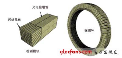
Figure 1: Schematic diagram of PET detector
Clock pulse distribution
In CT imaging and other similar data acquisition systems, the clock will limit the performance and data conversion effects of those time-based systems. In order to keep the high-speed clock clean, signals are distributed in differential forms such as LVPECL or LVDS. Because they are transmitted on the channel board, when driving the load (such as a large FPGA) and adjusting the board layout skew, the distribution of clock pulses will be affected, that is, the arrival time of edge pulses. To address this problem, semiconductor vendors have created clock distribution devices that allow engineers to "solve" the problem of skew through programmable delays and redrive of the clock signal. Figure 2 shows a block diagram of the National Semiconductor LMK01000 series clock pulse distribution device, which can not only control the correction deviation, but also control the programmable frequency divider, multiplexer and output driver. This is critical for achieving in-system programmable performance that can manage clocks and reduce timing errors.
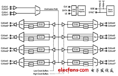
Figure 2: LMK01000 series clock pulse distribution device architecture block diagram
When transmitting clock pulses through the channel board, twisted pair or dual coaxial cable is required, but new problems will also appear. Because the transmission distance of high-speed signals is near or far, these signals will suffer from high-frequency attenuation, group delay, and other distortions caused by crosstalk and system noise, especially when high-voltage electric drive PMT is required. In most cases, the recovery of the clock pulse is done by retiming the phase-locked loop (PLL) device. For example, the LMK03200 accurate zero-delay clock regulator is used, which includes a high-frequency phase-locked loop, integrated VCO, and some features of the LMX01000.
Summary of this article
Large data acquisition systems such as PET, CT, MRI, and dual-mode scanners require strict clock control to minimize image distortion, system noise, and improve the overall performance of the system. New products with greater light output and faster decay time make it possible to use PET scanners for TOF testing. This latest technology requires a higher frequency clock, which produces higher resolution images. With the development of new technologies, the future of CT scanning will become brighter, but as the resolution of the detected images continues to increase, the timing rate will further increase, so clock distribution will be a long-term challenge for designers.
This range of extremely rugged 'skeleton' cable drums is particularly suited to life on the road but also at home in a TV or film studio. They are constructed from heavy-duty, welded, steel tubing, on to which an overall passivated zinc plate is applied. A traditional two-flange type is suitable for triax camera cable, multicore audio cable and heavy-duty power cables. An innovative three-flange design is suitable for coiling and protecting the inner 'tail' of SMPTE 311M hybrid fibre camera cable. An optional combined trolley and reeling stand is available for transporting the drums.
Skeleton Reel,Steel Tube Reel,Galvanized Reel,Studio Reel,Cable Trolley
NINGBO BEILUN TIAOYUE MACHINE CO., LTD. , https://www.spool-manufacturer.com