Introduction
Intermodulation Distortion (IMD) is a common metric used to measure the linearity of amplifiers, gain blocks, mixers, and other RF components. The second and third order intercept points (IP2 and IP3) are the quality factors of these specifications and can be used to calculate the distortion product at different signal amplitudes. Although RF engineers are very familiar with these specifications, they often create some confusion when used in ADCs. This tutorial first defines the intermodulation distortion in the framework of the ADC, and then points out some precautions that must be taken when applying the definitions of IP2 and IP3 to the ADC.
Two-tone intermodulation distortion (IMD)
When measuring two-tone intermodulation distortion, two pure spectral sine waves are applied to the ADC at frequencies f1 and f2, which are generally relatively close. Set the amplitude of each tone to be lower than full scale, and the value is slightly over 6dB, so that the ADC will not clip when the two phases are increased. The positions of the second and third order products are shown in Figure 1. Note that the second-order product is at the frequency position that the digital filter can eliminate. However, the third-order products 2f2-f1 and 2f1-f2 are close to the original signal, and filtering is more difficult. Unless otherwise stated, two-tone intermodulation distortion refers to these "close" third-order products. The intermodulation distortion product value is generally in dBc, relative to the value of one of the two original tones, rather than the sum of the two.
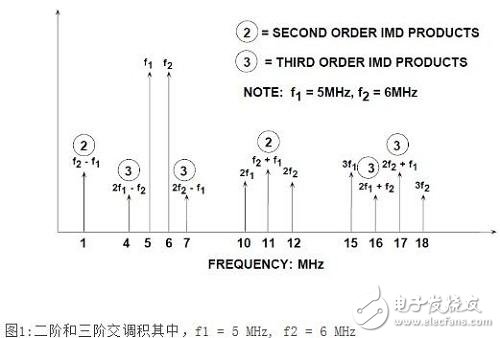
Note, however, that if the two tones are close to fs/4, the aliased third harmonic of the fundamental wave may make the identification of the true product of 2f2-f1 and 2f1-f2 extremely difficult. The reason is that the third harmonic of fs/4 is 3fs/4, and the aliasing occurs at the frequency of fs-3fs/4=fs/4. Similarly, if the two tones are close to fs/3, the aliased second harmonic may interfere with the measurement. The principle is the same as above, the second harmonic of fs/3 is 2fs/3, and the aliasing appears at fs-2fs/3=fs/3.
Second and third order intercept points (IP2, IP3), 1-dB compression points
The third-order intermodulation distortion product is particularly troublesome in multi-channel communication systems where channel isolation remains constant throughout the frequency band. The third-order intermodulation distortion product may mask the small signal in the presence of a large signal.
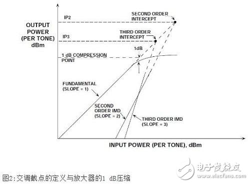
In amplifiers, mixers, and other RF components, the third-order intermodulation distortion product is typically represented by a third-order intercept point (IP3), as shown in Figure 2. Two spectrally pure tones are applied to the system. The output power of the tone (in dBm) and the relative magnitude of the third-order product (based on a single tone) are expressed as a function of the input signal power. The fundamental wave is represented as a slope=1 curve in the figure. If the system nonlinearity is approximated by a power series expansion, the second-order IMD (IMD2) amplitude will increase by 2 dB for each 1 dB increase in the signal, as shown by the slope=2 curve in the figure.
Similarly, for every 1 dB increase in signal, the third-order IMD (IMD3) amplitude is increased by 3 dB, as shown by the slope=3 curve in the figure.
Under a low-level two-tone input signal and two data points, second-order and third-order intermodulation distortion lines can be drawn, as shown in Figure 2 (the principle is that a point and a slope define a straight line).
However, once the input signal reaches a certain level, the output signal begins to soft limit or compress. One related parameter here is the 1dB compression point. This is where the output signal is compressed by 1 dB from an ideal input/output transfer function. In Figure 2, the point is in the region between the ideal slope = 1 line becoming a dashed line and the actual response showing signs of compression (solid line).
However, both the second and third order intercept lines can be extended to intersect the extension line (dashed line) of the ideal output signal line. These intersections are referred to as second- and third-order intercept points, denoted IP2 and IP3. These power level values ​​are usually based on the output power of the device that is conducted to a matched load (usually but not necessarily 50), expressed as dBm.
It should be noted that the IP2, IP3, and 1dB compression points are all functions of frequency. As expected, the higher the frequency, the more severe the distortion.
For a given frequency, the approximate level value of the third-order IMD product (as a function of the output signal level) can be calculated with the third-order intercept point known.
The concept of second and third order intercept points is not valid for ADCs because, in this case, the distortion product changes are unpredictable (as a function of signal amplitude). The ADC does not gradually begin to compress signals close to full scale (there is no 1dB compression point); once the signal exceeds the ADC input range, the ADC acts as a hard limiter, causing a sudden amount of distortion due to clipping. On the other hand, for signals far below full scale, the distortion bottom remains relatively constant, independent of signal level, as shown in Figure 3.
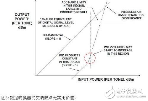
The IMD curve in Figure 3 is divided into three regions. For low level input signals, the IMD product remains relatively constant and is unaffected by signal levels. This means that when the input signal is increased by 1dB, the ratio of the signal to the IMD level is also increased by 1dB.
When the input signal is within a few dB of the full-scale range of the ADC, the IMD may begin to increase (but may not be the case in a well-designed ADC). The exact level at which this occurs depends on the specific ADC - some ADCs will not increase significantly in their full-scale input range, but most ADCs will. As the input signal continues to increase and exceeds the full-scale range, the ADC should act as an ideal limiter and the IMD product will become very large. For these reasons, the ADC does not have second- and third-order IMD cross-cutting point ratings. It should be noted that the DAC actually has the same situation. In both cases, the tone or multi-tone SFDR (spurious-free dynamic range) rating is a widely accepted measure of the distortion performance of the data converter.
Rainproof Cummins Diesel Generator
Waterproof Diesel Generator,Rainproof Cummins Diesel Generator,600Kw Cummins Rainproof Generator,600Kw Rainproof Cummins Diesel Generator
Jiangsu Lingyu Generator CO.,LTD , https://www.lygenset.com