The Bluetooth application model defines how to use a set of basic protocol standards to achieve interoperability, and it represents a specific application. The Bluetooth CTP application model includes BaseBand, LMP, L2CAP, SDP, TCS-B and GAP. BaseBand ensures the physical connection between the Bluetooth device units in the Bluetooth piconet by radio frequency; LMP (Link Manager Protocol) is responsible for the establishment of Bluetooth devices; L2CAP (Logical Link Control and AdaptaTIon Protocol) completes the disassembly of data, service quality and Protocol multiplexing and other functions are the basis for other upper-layer protocols; SDP (Service Discovery Protocol) provides a mechanism for upper-layer applications to discover the services and features available in the network; TCS (Telephony Control Protocol SpecificaTIon) provides Bluetooth device room Call control signaling for voice and data; GAP (Generic Access Profile) defines how Bluetooth devices discover each other and establish a connection, ensuring that the Bluetooth unit can discover which applications each unit supports through Bluetooth exchange information.
Figure 1 shows the Bluetooth protocol involved in the CTP application model.
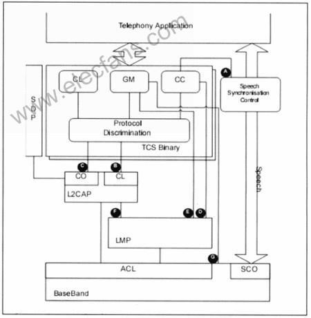
Figure 1 CTP model
In Figure 1, the AG interface functions are as follows:
(1) CC (Call Control) uses this interface to provide information on when to connect (or disconnect) the voice channel, perform voice synchronization control, and connect or cut off the internal voice path.
(2) CL (ConnecTIonless) interface is used to send and receive TCS-Binary broadcast messages: use point-to-multipoint signaling to send SETUP messages to L2CAP for transmission on a connectionless channel; L2CAP uses this interface to notify TCS that connectionless Received SETUP message on the channel.
(3) The CO (ConnecTIon) interface uses point-to-point signaling to send TCS messages to L2CAP for transmission on connection-oriented channels.
(4) CC uses this interface to control LM (Link Manager) in order to establish or release SCO links.
(5) When initializing and processing the key, GM (Group Management) uses this interface to control the LM.
(6) This interface is not within the scope of the CTP model.
(7) GM uses this interface to control LC (Link Control) and BaseBand to implement query, paging, query scanning and paging scanning.
Bluetooth supports SCO (Synchronous Connection-Oriented) links, eSCO (Extendend Synchronous Connection Oriended) links, and ACL (Asynchronous Connection-Oriended) links. SCO supports symmetric connection and point-to-point connection, transmits voice and other real-time information in the specified time slot; eSCO link is an extension of standard SCO, supports symmetric, asymmetric connection and point-to-point connection, supports more packet types of fusion, And more flexible selection of packet data and time slot; ACL link is mainly data, which can be transmitted in any time slot. When ACL transmission occupies the reserved time slot of SCO, once the system needs SCO transmission, ACL will automatically give up these time slots to ensure the real-time nature of SCO.
The Bluetooth radio frequency and baseband part establish a wireless channel between the terminal device and the AP (Access Point) by sending and receiving data packets. The Bluetooth terminal first uses SDP to discover that the AP provides a cordless telephone service, and then requests to use the service. The AP authenticates the terminal device requesting the service to decide whether to accept the request. After passing the identity verification, the Bluetooth terminal establishes the SCO or eSCO path through the CC interface, and wirelessly accesses the corresponding network through CTP to obtain the required information.
2. PSTN access solution
The Bluetooth PSTN access point is composed of two core chips, BC04 (Bluecore 04) and ASIC (Application Specific Integrated Circuit), and peripheral devices. Among them, BC04 serves as the master or controller role, and ASIC serves as the slave role. Both are connected through PCM and UART. , Used to transmit data flow and control flow, respectively. The corresponding Bluetooth protocol stack and application programs are stored in FLASH and EEPROM. The system structure is shown in Figure 2.
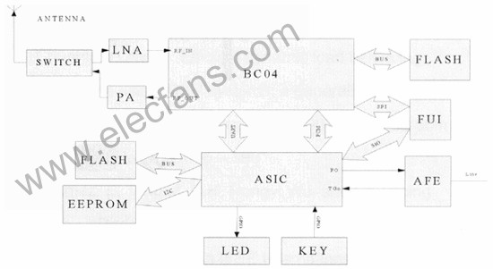
Figure 2 PSTN AP system structure diagram
Among them, BC04 supports a maximum of 4 active connections (including headphones), and supports two channels of SCO voice at the same time, so the voice can be sent to the analog side through PCM and ASIC PCM multiple channels, so as to achieve 3-party calls. The ASIC part realizes the mutual conversion of PCM voice data and analog voice signals, and is responsible for controlling the human-machine interface by sending and receiving PSTN signaling. It controls the input and output of LED and KEY through GPIO (General Purpose Input / Output). When BC04 needs to be notified, AT commands are sent through the UART port. AFE (Analog Front End) is composed of discrete components, including the transmission path and the reception path, and realizes automatic gain control of the reception path, so that the voice signal reaching the ASIC can reach a certain level and signal to noise ratio requirements. FUI (Firmware Upgrade Interface) realizes debugging and upgrading of ASIC.
The Bluetooth PSTN access point is connected to the PSTN line to provide users with wireless data voice access. AFE receives the voice signal from the PSTN line, through analog-to-digital conversion and ASIC processing, and finally converts it to CVSD (Continuously Variable Slope Delta modulation) data, which is sent out by the air interface of the Bluetooth module; , Transmit it to u-law PCM signal to ASIC, after ASIC processing and digital-to-analog conversion, and finally sent to PSTN line.
PSTN access point, through the establishment of a Bluetooth wireless piconet (Piconet) within a range of 100 m, provides wireless phone call in / out functions for Bluetooth-enabled voice terminal devices such as mobile phones and headsets; in voice terminal devices It can make wireless voice calls with the access point; it implements the CTP application model of the Bluetooth SIG specification, which enables Bluetooth mobile phones to enter the fixed telephone network as a cordless phone through the Bluetooth PSTN access point.
As shown in Figure 3, Bluetooth CTP MS (mobile station) and PSTN AP are used to connect to the fixed network through a local exchange. Among them, MS is a dual-mode terminal, which can pre-set which network to use to make calls according to the difference in tariffs of different networks. Within the Bluetooth coverage, according to the settings, CTP MS can automatically choose to use the fixed network or mobile network, and the selection strategy of the incoming route depends on whether the user has registered through the Bluetooth AP. Registered users will be able to dial to a fixed phone number; otherwise, they will dial directly to a mobile phone number. After the CTP MS is registered by the AP, when there is a call to the mobile phone, the Bluetooth access point and the Bluetooth mobile phone can ring simultaneously.
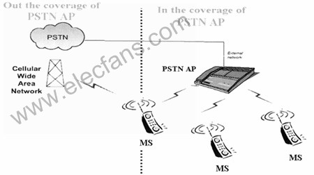
Figure 3 PSTN AP network structure diagram
In an indoor environment, that is, within the Bluetooth coverage area, the Bluetooth CTP MS establishes a connection with the AP and registers call transfer with the cellular network, and transfers the cellular phone call to the PSTN line to which the AP is connected. When the AP detects a call from the PSTN, the AP sends a signal to the CTP MS and establishes a path, and then the user can talk to the other end through the AP. When the CTP MS is not connected to the AP, the AP can automatically register the call forwarding function with the mobile network and transfer the call to the nearby Bluetooth gateway, thereby transferring the PSTN phone to the preset cellular network number, which can avoid Missed PSTN call.
In the outdoor environment, that is, out of the coverage of the Bluetooth network, the CTP MS can make and receive calls through the cellular network. When the CTP MS enters the Bluetooth network coverage area from the outside, without manual intervention, the MS can automatically register through the AP and transfer the cellular network phone to the line connected to the Bluetooth voice gateway to dial the PSTN network phone.
3. VoIP access solution
SIP (Session Initiation Protocol) is a signaling protocol designed specifically for IP phones, especially in conjunction with the Internet. It can establish, modify, or terminate multimedia sessions or calls, so it is widely used in VoIP.
As shown in Figure 4, a Bluetooth CTP mobile phone and a CTP-capable VoIP access point, namely CTP-SIP AP, are connected to the VoIP network through a broadband network. The VoIP network here supports the SIP protocol, the VoIP access point supports Bluetooth CTP and SIP protocols, and the MS does not need to have the SIP function. The CTP-SIP AP has two 10/100 M rate RJ45 Ethernet interfaces, one of which is used to connect a PC or LAN, and the other is used to connect a DSL router or WAN. We can also use a CTP-SIP gateway instead of AP and DSL / cable modem to achieve the integration of the two functions. At the same time, the gateway needs to support Bluetooth CTP, SIP, TCS Binary protocols, and has the functions of modulation, demodulation and routing.
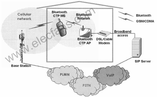
Figure 4 VoIP AP network structure diagram
Within the Bluetooth coverage, the AP first registers through the SIP server, and then the Bluetooth CTP mobile phone can choose to use a cellular network or a VoIP network according to the settings. Therefore, CTP mobile phones can be used as both IP phones and cellular networks as an ordinary mobile phone. Each AP can register multiple MSs. At the same time, each MS is assigned its own VoIP application model. When making a call, the AP establishes a path to the MS based on the VoIP number, thereby making an IP call.
Outside the coverage of Bluetooth, CTP mobile phones directly dial cellular phones. In order to ensure the seamless access of CTP mobile users, the method of adding a buffer in the AP can be used to reduce the packet loss rate. The specific implementation of this scheme is as follows: When the Bluetooth user moves the location, if the Bluetooth user's received signal strength ( RSSI) When it is less than a certain threshold, it will issue a query command to find if there is a closer AP, and it will also issue a statement to the original AP, telling it that it will switch to the new AP. Before the registration request of the Bluetooth user moving to the new AP is not confirmed by the current AP, the current AP stores the data packet sent by the communication peer in the buffer. After the registration request is confirmed, the current AP sends a confirmation message to the Bluetooth user through the new AP, and at the same time refreshes the care-of address of the communication peer, so that the communication peer obtains the new care-of address of the Bluetooth user, and sends future data packets to the new AP , And then forwarded to Bluetooth users. After receiving the registration confirmation message, the Bluetooth user cancels its registration in the old AP, and notifies it of the new care-of address, so that it releases the buffered data packet to the new AP, and then forwards it to the Bluetooth user, thus avoiding switching When the data is lost.
4 Conclusion
The above two application solutions aim at the perfect IP network in developed countries and the PSTN telecommunication network in developing countries, make full use of existing network resources, and achieve the integration of fixed and mobile networks with little investment.
The integration of numerous application models of Bluetooth technology simplifies the entire system structure, thereby making CTP more widely used in the FMC access network and more complete functions. Therefore, we can optimistically say that the application of the Bluetooth CTP solution in the FMC access network will win the favor of more and more operators.
There are 10 series of products,with over 1,100 types and 12,000 models of Terminal Blocks . We have many types of Terminal Blocks , such as Pluggable Terminal Blocks,PCB Universal Screw Terminal Blocks,PCB Spring Terminal Blocks, Transformer Terminal Blocks,Through-Wall Terminal Blocks, Interface Module ,Feed-Through Terminal Blocks, Barrier Terminal Blocks , Din-Rail Terminal Blocks and Terminal Blocks Independent Parts.Our products have been approved by UL,VDE,TUV,EXCE,CQC,RoHS,REACH.
We also have rich experience in terminal strip assembly, and we have experience in the installation of dozens to hundreds of terminals. As long as it is in terms of terminal strip assembly, we can meet it.
Terminal Block Assembly
Din Mount Terminal Block,Terminal Block Assembly,Terminal Board Assembly,Din Rail Mount Terminal Block
Suzhou WeBest Electronics Technology Co.Ltd , https://www.webestet.com