introduction
This article refers to the address: http://
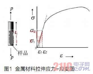
Strain is an important parameter in material testing. An important research area of ​​material mechanics is to establish the stress-strain relationship of materials as shown in Figure 1. Study and predict the mechanical behavior of materials [1], so the acquisition of strain is related to whether it is correct and Effectively construct the constitutive equation of the material. In experimental mechanics, strain is not directly measured, it is calculated by measuring the absolute deformation of the material and then according to the corresponding strain definition.
In practice, a mechanical extensometer is usually used to clamp the workpiece, and the load is applied while the workpiece is being loaded. For rigid materials, strain can generally be measured using a conventional mechanical gripper extensometer. However, such devices cannot be used with workpieces of soft plastic materials such as fibers, films, foams, etc., because their weight and clamping methods affect the test results and break points. In practical situations, it is necessary to measure the performance of the oversized strain range until the material is broken. Due to the stroke limitation, the mechanical extensometer needs to be used under certain environmental conditions, such as high temperature conditions, mechanical extensometers. It will also be restricted.
In order to reduce measurement error, improve measurement accuracy and improve the practical range. In the context of the material tensile test, a video strain measurement system was designed and used to indirectly measure the strain that changes in real time during the tensile test of the material. The strain measurement system must satisfy the measurement accuracy of the test and ensure the real-time measurement. In this paper, the precise edge detection calculation [2,3] method of strain measurement in material tensile test is deeply studied. Under the mature wavelet transform theory, the wavelet transform expectation sub-pixel algorithm is applied to the design of video strain measurement system.
Wavelet transform expectation subpixel positioning method
Wavelet analysis is a multi-resolution analysis [4]. It can highlight the local features of signals in the time domain and frequency domain. It has been widely used in image processing such as denoising and edge detection.
Wavelet transform edge detection principle
The one-dimensional wavelet function is expressed as follows:

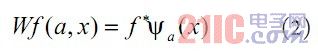
The wavelet transform of the image function f(x) at the wavelet scale a is obtained by convolution operation:
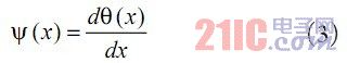
For some special wavelet functions, the modulus maximum of the wavelet transform corresponds to the sudden change of the signal. Let be a smooth function, defined as the first derivative:
Note that the wavelet transform at the wavelet scale a is:
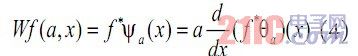
The wavelet transform is proportional to the first derivative of the smoothed function f(x), and the maximum value corresponds to the maximum value of the derivative. It is also the local mutation point of the signal at the wavelet scale a. Therefore, wavelet transform modulus maximum detection can be applied to edge detection of images [5].
Principle of Wavelet Transform Expectation Subpixel Positioning Method
Set the one-dimensional ideal edge model to:
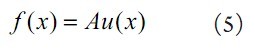
among them,
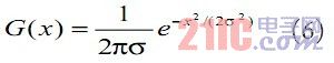
For an actual imaging system, since the CCD is an integrating device, its output gray value is related to the light intensity distribution on the photosensitive surface. Let G(x) denote the imaging system point spread function, which can usually be approximated by a Gaussian function:
The ideal edge noise-free image acquired by the imaging system is:
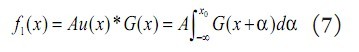
Where: x0 is the exact location of the edge image.
Let wf1(a, x) denote the wavelet transform coefficient at the wavelet scale a, and p(x) is the wavelet transform coefficient probability greater than the given threshold T. The exact position of the edge image after CCD imaging (with actual noise) is derived.
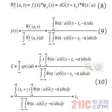
The expected value is the exact position of the edge of the actual image obtained by the ideal edge through the imaging system.
For discrete signals, it is assumed that the wavelet transform coefficients of the image edge signal are greater than a given threshold T, and E is the expected value of the step edge position x, then:
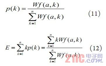
The expected value of the wavelet coefficient E thus obtained is the exact position of the edge of the image.
Wavelet transform expectation value sub-pixel positioning method solving step
The specific positioning steps of wavelet transform expectation sub-pixel edge detection are as follows:
1) selecting a wavelet scale a to perform wavelet transform on a given data;
2) Find the modulus maxima of the wavelet transform coefficients at the wavelet scale a;
3) filtering out the modulus maxima of the wavelet transform coefficients which decrease with the increase of the wavelet scale a due to noise;
4) Given a threshold T, filtering out the modulus maxima generated by noise and minute details;
5) Near the modulus maximum value, find the wavelet coefficient interval of the same sign as the modulus maximum value. The wavelet transform coefficient in the interval is obtained by the equation (12), and the expected value is the sub-pixel position of the image edge.
The theory can prove that the wavelet transform edge detection and positioning method has no principle error and has strong anti-noise performance. Relevant experiments have shown that the accuracy of edge location detection can be within 0.02 pixels without special requirements on environmental conditions such as light source [5], which verifies the correctness of the theory. In addition, the wavelet transform expectation edge detection sub-pixel localization method is based on the signal wavelet transform, and the Mallat method is proposed to make the wavelet transform speed greatly improved [4], so the wavelet transform expectation edge detection sub-pixel localization method, regardless of It has superior performance in terms of its accuracy, anti-noise performance or speed.
Measurement test and results
Test equipment and system software design
Test hardware: CCD - Basler A601f, Germany; lens - Computar's H6Z0812 lens; image processing card - Matrox's Meteor-II/1394 card; light source - homemade LED surface light source. A dynamic tensile test was carried out using a material testing machine during the test. The specific parameters of the material testing machine used are: the force measurement accuracy is within the range of 0.4% to 100% of the load sensor capacity, the accuracy is ±0.5% of the indicated value; the displacement speed accuracy is better than ±0.5% (the no-load, the detection distance is greater than 20mm). The test equipment is shown in Figure 2:
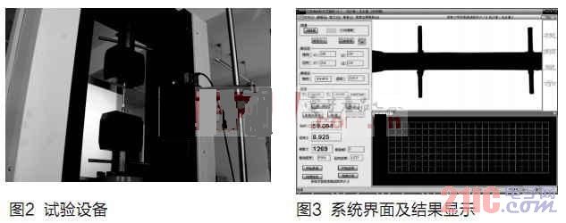
Under the Windows XP operating system, using Visual C++ high-level language programming system software [6,7], the algorithm operation, system interface and display results are shown in Figure 3.
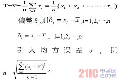
According to the precision evaluation method of the test data, in the test, the obtained measurement value M is composed of the true value T and the experimental error δ, that is, M=T±δ. The true value is unknown, and the arithmetic mean is usually used as the true value by multiple measurements.
Influence of acquisition frequency on system algorithm implementation
The video strain measurement system is applied to dynamic image measurement. Therefore, the time factor affecting the system data result needs to be studied, that is, the influence of different acquisition frequencies on the accuracy of the wavelet transform expected sub-pixel algorithm is analyzed.
Test conditions: The tripod is placed on the testing machine, and the camera is fixed. It is about 200mm away from the test piece. The specific distance is adjusted according to the clarity of the workpiece image. The device is shown in Figure 2, and the extensometer is used as the mark. The test machine was turned on, the test was started, the moving beam was moved downward, the moving speed of the selected beam was about 3 mm/min, the workpiece entered the tensile test stage, and the camera collected test data for analysis and calculation. The specific test parameters are as follows: tensile speed of test machine 3mm/min; illuminance 726LUX; object distance 192mm; measuring gauge length 50mm; aperture 5; focal length 14.
1, the acquisition frequency of 15 frames / sec
In Fig. 4, in the data collected by the camera, the number of frames is converted into time, which matches the time collected by the testing machine as the abscissa, the ordinate is the deformation value, the dashed line is the data collected by the extensometer, and the solid line is the data collected by the camera. .
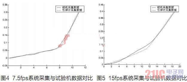
When the acquisition frequency is 7.5 frames/second, the average error of the camera acquisition data and the data collected by the extensometer is:
![]()
2, the acquisition frequency of 15 frames / sec
The same as above, when the acquisition frequency is 15 frames/second, the average error of the camera acquisition data and the data collected by the extensometer is:
![]()
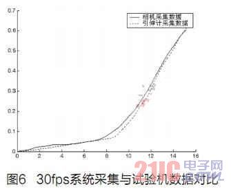
3. The acquisition frequency is 30 frames/second.
When the acquisition frequency is 30 frames/sec, the average error of the data collected by the camera and the data collected by the extensometer is:
![]()
By analyzing the data results of the video strain measurement system at different image acquisition frequencies, it can be concluded that the camera acquisition frequency (7.5 frames/second, 15 frames/) under the condition that the external factors such as illumination, object distance and focal length are constant. In seconds, 30 frames per second, the data error will increase. However, the system can meet certain error requirements at 30 frames/second without excessive errors, making the measurement results inaccurate.
Conclusion
The wavelet transform video strain measurement system designed in this paper has high precision and certain real-time requirements, which can meet the actual needs. With the development of electronic technology, mechanical science, optics and computer science and technology [8], the sophisticated edge detection technology applied to video strain measurement systems will have a long-term development.
Ridging Machine for Agriculture:
ridging machine for Agriculture can improve the ground temperature and increase the air permeability of the soil, and our ridgers are versatile and used in farm land which is welcomed by ploughing farmers for its plurality of unique advantages. These ridging tractors are of small resistance and high efficiency. Our ridging machine also has advantages of racing against time, saving labor, working efficiency and low cost etc.

Ridging Machine for Agriculture Technical Parameters:
1. Weight: 240KG
2. Operating width: 1400 mm
3. Power: 36.8-51.8 KW
4. Size: 920*1690*1020 (mm)
Typical Applications: can be worked in paddy field, dry land, hilly ground and green house.
If you have any questions, please contact us directly. Crawler tractor for agriculture are produced by Hunan Nongfu with high quality and good appearance.
welcome you can visit our factory for inquiry, please send mail directly to us.
Ridging Machine for Agriculture
Agricultural Machinery, Ridging tractor, Ridger, ridging machine
Hunan NongFu Machinery&Electronic.Co., Ltd. , https://www.nfagmachine.com