Improving fuel economy in vehicles through the electrification of power units is a critical technology for meeting increasingly strict fuel efficiency regulations. However, only a limited number of small vehicles, such as Class B models, incorporate electric systems because the fuel economy gains are relatively modest compared to the added costs and the need for additional installation space. This paper explores the optimal design of a strong hybrid system tailored for small vehicles.
To maximize energy efficiency, the study analyzed engine and transmission efficiency distribution across different driving modes and selected an appropriate automatic transmission suitable for small vehicles. When evaluating hybrid system functions, the motor-generator connection mode and motor output power were determined based on both fuel economy and drivability. Additionally, to ensure smooth torque delivery during gear shifts and reduce shaft length compared to traditional manual transmissions, the arrangement of the motor-generator and transmission gears was optimized.
A prototype of a mechanical automatic variable-speed hybrid system and a test vehicle were developed. The shift sequence that enables seamless torque delivery and flexible driving performance was introduced, along with evaluation results from real-world testing.
In recent years, due to concerns over global warming and rising energy consumption, fuel economy regulations have become more stringent. Electric power units have been widely adopted to improve fuel efficiency, leading to the development of various hybrid systems. However, only a small number of small vehicles utilize advanced electric systems like strong hybrid configurations. This is primarily due to the limited improvement in fuel economy relative to the increased cost and the requirement for extra installation space.
This study presents the verification results of a hybrid system specifically designed for small vehicles, including a mechanical automatic transmission (HV-AMT) developed by Aisin Seiki Co., Ltd.
**1. Hybrid System Selection**
Electric power units are typically categorized based on their level of electrification and functionality (Figure 1). Considering future fuel economy regulations, this paper focuses on strong hybrid systems. To select the most suitable system configuration, energy efficiency was evaluated by combining engine and transmission efficiency.
To enhance engine efficiency, the engine is operated in its most efficient range (optimized operating conditions). A continuously variable transmission (CVT) can achieve this. Figure 2 shows simulation results of a 1.0 L engine vehicle operating under LA4 driving conditions.
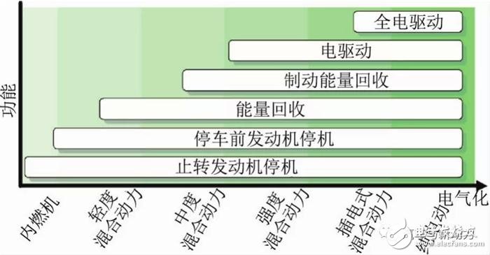
**Figure 1: Electrification and Function**
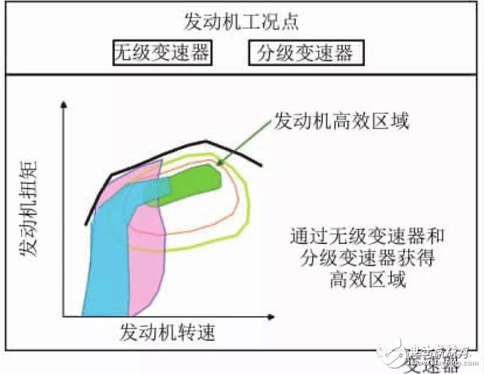
**Figure 2: Engine Operating Point During LA4 Mode Operation**
As shown in Figure 2, small vehicles typically operate in the engine's efficient zone even during certified drive cycles like LA4. In this context, CVT offers a slight advantage over step-variable transmissions.
Table 1 outlines the transmission efficiency characteristics of typical systems. Mechanical automatic transmissions (AMT) and dual-clutch transmissions (DCT), which use hydraulic pressure only during shifting, exhibit the highest efficiency. Automatic transmissions (AT) maintain efficiency via torque converters, while CVTs, which rely on pulleys and steel belts, have the lowest efficiency.
**Table 1: Typical Transmission Characteristics**
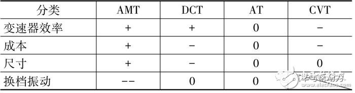
**Note:** [0] reference; [+] advantage; [-] disadvantage; [--] great disadvantage
While AMT offers the best cost and form factor, it can cause shift shocks due to torque interruption. Other transmissions do not face this issue.
Based on these findings, Figure 3 presents the energy efficiency simulation results (engine efficiency × transmission efficiency) for a 1.0 L engine vehicle.
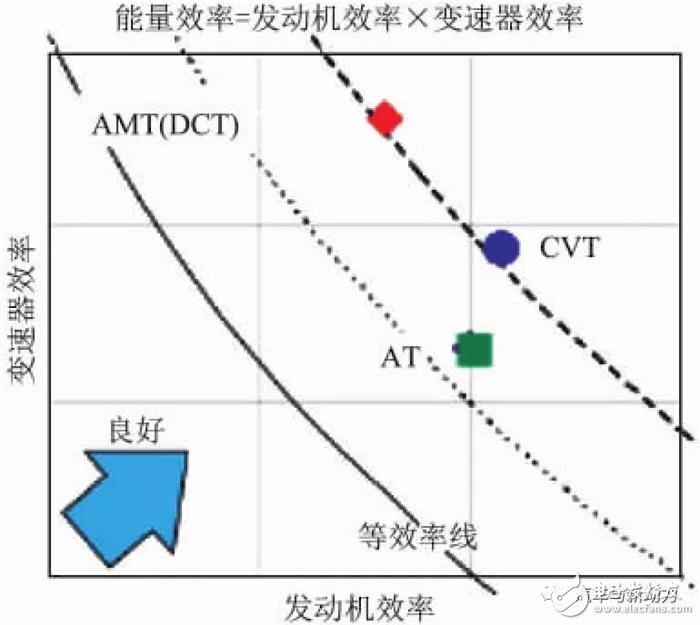
**Figure 3: Energy Efficiency Simulation Results**
As seen in Figure 3, AMT, DCT, and CVT demonstrate the highest energy efficiency. AT has better engine efficiency than AMT and DCT due to the larger transmission ratio set by the torque converter.
Considering these results, AMT was chosen as the base transmission for the hybrid system due to its high efficiency and low cost. To eliminate shift shocks, a motor is used as auxiliary power during gear changes.
**2. Design Concept**
**2.1 High Motor/Generator Connection Point**
When determining the drive unit structure, various motor/generator (M/G) connection points were analyzed for their functional capabilities. The comparison of different connection points is shown in Figure 4.
The input shaft connection places the M/G between the engine and transmission, allowing the engine to be disconnected via a clutch. The output shaft connection places the M/G on the transmission output shaft. The input and output shaft connections position the M/G on the third axis, enabling disconnection from either the input or output shaft. The rear wheel connection mounts the M/G on the rear drive shaft.
Given the need for auxiliary power during HV-AMT shifts, the "Input and Output Shaft Connections" with the best hybrid function were selected.
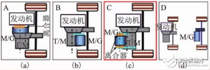
**Figure 4: M/G Connection Point Comparison**
**2.2 High M/G Drive Performance**
Carbon Fiber Rigid Felt Tube,Vacuum Furnace Insulation Cylinder,Carbon Fiber Thermal Insulation Cylinder,Heat Insulation Screen Of Vacuum Furnace
HuNan MTR New Material Technology Co.,Ltd , https://www.hnmtr.com