As handheld voice communication devices become more popular, their opportunities for use in noisy environments are increasing, such as airports, busy roads, and crowded bars. In such a noisy environment, it is difficult for both parties to the call to hear what the other party said.
This article refers to the address: http://
In addition, many communication systems use computer-based speech recognition, command and/or response systems. These systems are susceptible to background noise. If the noise is too large, the system will be greatly deviated. Therefore, it is necessary to improve the ratio of the speech signal to the background sound noise.
This article will explain the basic principle of using a microphone array to eliminate background noise in a voice communication system, and cites National Semiconductor's LMV1088 microphone array amplifier as an example.
Microphone array
Microphone arrays are those in which a plurality of microphones are arranged one after another in a special pattern, allowing them to work together to produce a composite output signal or sets of signals.
Each microphone is a sensor or a spatial window for receiving (spatial sampling) input signals. The overall response of the array is the superposition of the individual responses of each microphone in the array and is related to the algorithm used.
The "array processing" algorithm used for multiple sets of microphone signals in an array is determined by several factors, including the spacing and arrangement of the microphones, the number and type of microphones, and the principle of sound propagation.
The basic task of the microphone array is to eliminate the ambient noise of the speech input signal, thereby improving the speech quality of the hearing aid system, speech recognition equipment and telecommunications products. In addition, the microphone array can also be used for orientation positioning and to calculate the distance between the sound source and the array.
The main function of the microphone array in the voice communication system is to provide a high quality voice signal while reducing the noise of the scene and the surrounding environment. The quality referred to here means that the final speech signal is very natural and true, and there are no artificial noises such as clicks and clicks, unintended silence, frequency distortion, echo or due to enhanced speech signal processing methods. Unscheduled signal level changes.
For the above reasons, the Signal to Noise Ratio Improvement (SNRI) is not the only parameter in selecting a background noise suppression solution, but other issues must be considered.
Sound information
Sound pressure level
The sound pressure level (SPL) decreases as the distance of the sound source increases. Figures 1 and 2 show the SPL reduction, respectively, in decibels (dB) and are a function of the source distance "x". When people talk, the position of about 1 cm from the lips is generally used as the reference point, and the SPL of the position is set to 96 dB. Under these conditions, the formula for SPL should be:
dB=96-20 log(x/0.01)
Or can be written as
dB=96+20 log(0.01/x)
The (or) in the formula is a reference value distance of 0.01 m, that is, the distance "x" with respect to the sound source in units of meters is 1 cm.
 |
figure 1 |
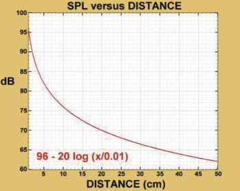 |
figure 2 |
When the distance "x" is doubled, the SPL of both curves is reduced by 6dB. Figure 1 is 200 cm away from the sound source, while Figure 2 is a partial enlarged view of 50 cm from the sound source. It can be seen from the figure that the sound pressure will drop rapidly due to the increase of the distance from the sound source, even in the case of a short distance. . For example, when the distance from the sound source is 10 cm, the SPL is reduced by 20 dB, that is, from 96 dB to about 76 dB.
Near field to far field sound
The near field of the sound source means that the position is within a wavelength range of the associated lowest frequency signal. Assuming that the minimum frequency of the associated speech is 300 Hz, such a wavelength λ is equal to c/f or 331.1/300, or 1.104 meters, where c represents the horizontal velocity of the acoustic wave at zero degrees Celsius. When the frequency is 3500 Hz, λ is equal to c/f or 331.3/500, or 0.0946 m (9.46 cm). Thus, the typical near-field range of a speech signal is about 9.5 cm to 1.1 m from the source.
At distances greater than 1 meter, the speech signal is considered to be the far field of the speech source. For arrays with close microphone spacing, the near-field source will exhibit a spherical wavefront with strong signal amplitude, pressure gradient, and the distance between the microphones and the sound source in the corresponding array. Frequency related differences.
Now suppose that the two microphones are separated by a distance of 3 cm, and the closest one to the sound source is 5 cm from the sound source. Figure 2 shows the first microphone (the one closest to the sound source), which senses an audio signal with an SPL of 82 dB, while the second microphone (that is, 8 cm from the sound source) senses a signal of 78 dB SPL. . Even if there is only a 4 dB difference between the two, the difference is still quite large relative to the overall signal level.
From the perspective of spectral content, all near-field speech signals within the microphone array are closely related. The amplitude of the microphone signal furthest from the sound source will be reduced compared to the microphone closest to the sound source, and the time delay from the most recent microphone to the farthest microphone will occur. However, it is not difficult to recover the speech signal in the case.
Sound sources outside the near-field range of the microphone array speech will be treated as far-field sources and exhibit a substantially planar wavefront for closely aligned microphones in the array. Each microphone in the array senses almost the same sonic energy and random phase signals, but the signals do not correspond unless the distance between the microphones is very close. If these signals are farther away from the microphone, the absolute SPL value of the microphone will drop further.
Another example is given. If the same microphone array is placed at a distance of 150 cm (1.5 m) from the sound source, the SPL value of the nearest source microphone will drop to 52.5 dB, and the distance source is 153 cm. The SPL value of the farthest microphone is slightly reduced to 52.3dB. Although there is only a 0.2dB difference between the two, the overall signal level from the sound source to the nearest microphone will drop by 30dB.
Different signals between the microphone outputs, after proper processing and filtering, can eliminate far-field noise, so that the composite output and processing circuits of the two microphones can provide high-definition speech signals.
Characteristics of sound and noise
The noise field here can be divided into three types, namely coherent noise, incoherent noise and diffusion noise.
Coherent noise refers to any form of reflection, scattering, or attenuation that occurs during the process when sound waves are transmitted to the microphone due to obstacles in the environment.
Incoherent noise means that noise at a certain location has nothing to do with noise at other locations and is considered as spatial white noise.
Diffused noise refers to noise that has the same energy and is axially incident in all directions. Examples include noise in the office, airport terminals and traffic noise, in other words, all noise-filled environments.
There are two kinds of sound noise referred to here, namely steady state noise and unsteady state noise.
Steady-state noise means that the energy of the noise is relatively stable, has a known and slowly varying spectral content, and is predictable. Examples include noise from the engine, air conditioning fans, random or "white" noise, and more. The noise suppression algorithm can effectively suppress such noise.
Unsteady noise means that the volume and sound content will change in a short period of time, such as loud speaking or yelling, passing sounds of a car or clapping, etc., which is unpredictable. If such noise occurs, they may automatically disappear before being recognized and suppressed. Unsteady noise is generally included in the steady-state noise.
The most troublesome situation is when the noise source has the same appearance time, spectrum and coherence characteristics as the speech signal, which occurs when the background noise is unsteady and is spoken by other people, such as in restaurants and bars. The station and the party are superior.
the second part
Microphone array solution
Depending on the method chosen, the microphone array solution can be a very efficient technique for suppressing steady-state and unsteady noise.
With appropriate algorithms, the individual microphone signals in the array are filtered and combined to achieve beamforming or spatial filtering, resulting in a complex microphone array polarity response pattern that can be pointed at or away from a sound location. Therefore, the sound at a certain location can be isolated or enhanced, or it can be suppressed or rejected. Similarly, signal correlation in the microphone channel can find the direction of the primary signal and its correct location.
Depending on the complexity and application of the array, the array can be controlled via an analog circuit equipped with a digital signal processor, plus appropriate computer software and a range of methods.
Beamforming
Beamforming is divided into two techniques: adaptive and directional.
In adaptive beamforming, the direction of the beam can be adjusted by data correlation filtering and changing the time response to the data. Several methods have been developed for adaptive beamforming. Although the processing of the signal is complicated, the advantage is that the design flexibility is higher, including the number, type and spacing of the microphones. Adaptive beamforming typically requires a digital signal processor or computer software to implement.
As far as directional beamforming is concerned, the direction of travel of the beam is optimized according to the orientation of the associated sound source, and noise from other directions is also excluded. In general, a differential microphone end-fire array with tight alignment and inherent directionality relies on fixed time delay or other methods to change the direction of the beam. For this type of application, any filtering and signal processing methods must be optimized for special mechanical designs. Directional beamforming typically requires analog circuitry, digital signal processors, or computer software to implement.
For voice applications, directional beamforming solutions are better, especially when the application involves speech recognition. If implemented in analog circuits, they should:
â— Real-time response to noise input
â— Easy to implement and no need to develop any algorithmic programs
• Provides an acceptable signal-to-noise ratio improvement (SNRI) value for suppressing steady-state and unsteady noise
â— Very low distortion in the absence of speech and improved mean opinion score for voice quality testing (ITU-T P.835)
â— Low computational complexity and low signal delay
â— Power consumption is smaller than other solutions
The disadvantages of adaptive beamforming with digital signal processors or software compared to orientation schemes are:
â— When implementing and adjusting the suppression algorithm, it takes time to repeat the identification and convergence noise.
â— Although it can provide better SNRI values, it usually brings more problems to the voice output signal, including delay due to noise convergence time, clicks and clicks, unintended silence, frequency distortion, Echo or irregular signal level changes associated with subband frequency signal processing methods
â— It is difficult to implement because of the need to develop a separate calculation program
â— Need more power consumption
All beamforming solutions use very small arrays that are sensitive to errors, including errors caused by microphone gain and phase mismatch, and because the audio signal path is embedded in the product rather than in the atmosphere. Path deviation. Therefore, the beam solution must have some form of compensation that can be placed within the beamforming system or with appropriate microphone and audio signal paths outside the system.
Microphone interval
The Nyquist spatial sampling rate is one-half of the wavelength of the highest frequency of interest (d = λ/2). In order to obtain a wavelength sample of the relevant frequency from space, the two sensors (ie the microphone) must be separated by one-half of the wavelength.
However, when the sensor spacing is less than one-half of the wavelength (d < 1/2λ), oversampling occurs, causing the wavelength to be sampled more than twice. Conversely, if the distance is greater than one-half of the wavelength (d > 1/2λ), spatial undersampling occurs, when the first sensor is sampled at the second sensor after sampling one wavelength. Restart before. Spatial undersampling can alias higher frequency signals to the associated frequency band, causing confusion in the results. In order to prevent aliasing, the bandwidth of the sampler must be limited to the highest relevant frequency.
Many studies have pointed out that if the distance between the sensors can be minimized, an efficient array of microphones can be created, and the distance can be much smaller than the minimum requirement of the Nyquist rate. Here is another example in which the spacing of the sensors is one-eighth of the wavelength of the associated sound wave.
In a pure speech system, the frequency range is 300 Hz to 3500 Hz, and the maximum sound energy can occur between 500 Hz and 2500 Hz. Under this condition, the interval of λ/8 is 1.18 cm at 3500 Hz and 1.65 cm at 2500 Hz.
Due to the increased wavelength, audio signals below 3500 Hz and 2500 Hz are still oversampled, so an interval of 1.18 cm or 1.65 cm can effectively acquire more signal samples.
Another calculation method sets the interval to two centimeters, so when the frequency is 2500 Hz, the wavelength interval (λ) / (c / df) is:
λ/(331.1/0.02*2500)=λ/6.62
If the spatial sampling rate is still below λ/2 at the highest correlation frequency, then the microphone spacing needs to be adjusted to meet the application requirements of the product. However, as the interval becomes more and more crowded (the spatial sampling rate is getting higher and higher), the coherence between the far-field signals in the microphone array becomes larger, so that the array can achieve better overall background noise suppression performance at each frequency. . Conversely, if the interval becomes wider, the overall rejection of the array will decrease, making it difficult to react to lower frequency signals.
Once the sensor spacing is determined, the array can be optimized for the frequency requirements. If a directional beamforming scheme is used, the response mode of the array must also be fixed at the same time.
Regardless of the product, some trade-offs must be made during the design process, including between the operating frequency range and the desired noise suppression level, between the theoretical and actual microphone spacing, and the overall array system cost and complexity. Wait.
Example of a microphone array solution
The following is an example of National Semiconductor's far-field suppression microphone array amplifier LMV1088 as a microphone array solution that provides up to 20 dB of background noise rejection for speech applications. The LMV1088 is an analog directional beamforming solution for differential dual microphone end-fire arrays with omnidirectional microphones.
The two microphones in the figure are located on two lines that are about 1.5 cm to 2.5 cm apart, or maintain an equivalent acoustic path distance. The distance between the speaker and the microphone of the mobile phone or earphone is preferably 2 cm to 10 cm. By using Fig. 1 and Fig. 2, the loss of the speech signal with distance can be calculated.
The LMV1088 not only provides initial compensation for the difference between the sound, microphone and amplifier signal paths on the two channels, but also performs a modified filter to make the speech output more natural and provides bandwidth-limited filtering.
Since the internal amplifier gain can be adjusted by the I2C command, microphones of different sensitivities can be used and the output signal level of the LMV1088 can be matched to the requirements of the analog input channel signal for a wide variety of communication processors and devices.
The LMV1088 supports four modes of operation and is selected by I2C commands:
◠Preset mode – use two microphones simultaneously for noise suppression
◠Stand-alone mode – use microphone 1 or 2 independently (no noise suppression)
◠Sum mode – the outputs of the two microphones are added together to give the microphone signal a 6dB gain (no noise suppression)
The analog features of the LMV1088 provide features not found in traditional DSP solutions:
â— No extra time is required to perform noise convergence calculations due to the background noise level and its type, which provides real-time response to speech signals and background noise, and eliminates annoying short-lived speech disappearance;
â— Since the sub-band frequency processing algorithm is not used, frequency distortion, clicks and clicks or other artificial false signals are not generated at the output;
â— Enhance mono echo cancellation processing in current systems
Comparison and testing of different microphone array solutions
In order to accurately compare and measure the effects of different background noise suppression schemes, all test setups and conditions must be consistent in order to obtain reliable results.
For the above reasons, several standard tests have been specially arranged, most of which are P0056e, 58e, 64e, 0830e and ITU-T P835 of the International Telecommunications Union Standard ITU-T Rec.
ITU-T P835 is designed for subjective testing and can effectively assess the quality of speech output in the system, including the effectiveness of noise suppression. This specification clearly states how to evaluate the subjective quality of speech in a noisy environment and is particularly well-suited for evaluating noise suppression algorithms. The method uses an independent grading standard to divide the test into three separate parts, which are independent of the subjective quality of the individual speech signals, the subjective quality of the individual background noise, and the overall speech quality (average opinion score) with background noise. evaluation of.
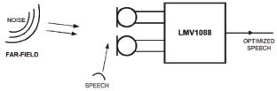 |
Figure 3 Noise, far field, speech, optimized speech |
As for the IEEE standard, tests of IEEE 1209-1994 and IEEE 269_1992 can be used. The former is specifically for measuring the transmission effect of telephone handsets and headsets, while the latter is for the transmission of analog and digital telephones. Both standard documents have been replaced by the IEEE 269-2002 document.
By combining the above criteria, objective numerical measurements can be achieved, and the subjective speech quality and electronic speech recognition of different background noise suppression solutions can be accurately evaluated.
In general, the system's noise suppression data is provided by the manufacturer, which may be the optimal level that the system can achieve, but for some applications that require high voice quality, these preset levels may not be sufficient for the application. demand.
Therefore, it is difficult to indicate the noise suppression value on the solution data sheet, and sometimes it is sometimes misleading unless all test conditions can be clearly stated. In this respect, the general data table does not provide very detailed data, even if it is provided is not practical, because it is difficult to imagine the conditions of the customer application exactly match the test conditions on the data sheet.
Golf Trolley Battery,12V Ups Battery Pack,Lithium Ion Ups,1000W Ups Battery
ZHEJIANG TIANHONG LITHIUM-ION BATTERY CO.,LTD , http://www.tflbattery.com