0 Introduction GPS (Global Positioning System) is developed for the navigation and positioning of various transportation and mobile equipment at sea, on land and in the air. It has the advantages of high precision, all-weather, global and no need to look through the point, making measurement technology A qualitative leap has taken place. After the introduction of GPS technology into China, especially in the United States after the cancellation of the SA policy, the development has been very rapid in recent years. At present, GPS has been widely used in many fields such as engineering surveying, geographic mapping, transportation and military, and has achieved obvious social and economic benefits, and its development prospects are very broad. In the industrial application of GPS, the data receiving system is the most basic equipment. The current data receiving system has a trend of increasing intelligence and scalability. The performance of the embedded MCU is getting stronger and stronger, and the peripheral interfaces are more and more abundant, but the cost of hardware and software is rising, which slows down the civilians of the GPS receiving system. Trends. This paper introduces a GPS data receiving system based on AVR microcontroller ATmega16 and Motorola M12 Oncore module.
This article refers to the address: http://
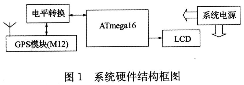
1 system hardware design The system consists of ATmega16, M12 module, LCD display and some peripheral circuits. The hardware structure of the system is shown in Figure 1. ATmega16 has a full-featured asynchronous serial communication interface (UART) with an I/O operating voltage range of approximately 0 to 5V when powered from DC 5V. The M12 module provides an input control information and output positioning and status information. Serial communication interface, when DC 3V power supply, its I / O level meets the TTL level range, 0 ~ 3V. Therefore, the ATmega16 serial interface can be connected to the serial port of the M12 module after being switched by the level conversion circuit for asynchronous serial data exchange. The system uses a 16 × 2 character LCD to display latitude and longitude information. The ATmega16 and LCD in the system are powered by DC 5V. The 5V power supply is supplied to the M12 module after the voltage is converted to 3V through a voltage regulator circuit consisting of a three-terminal regulator chip LM317.
1.1 Hardware Interface of ATmega16 and M12 Modules Because the I/O operating voltage range of ATmega16 and M12 modules is different, the serial port between the two needs to be level-converted to ensure stable communication. Figure 2 shows.
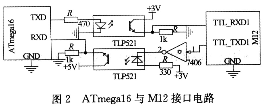
Here, the photo-coupled device TLP521 is used to perform level shifting between 5V and 3V to enhance the anti-interference ability. The ATmega16 has a strong I/O drive capability (maximum output of 40mA) and can directly drive the TLP521. The I/O drive capability of the M12 module is weak. It is necessary to add a driver buffer to drive the TLP521. Here, the 7406 inverting driver buffer is used.
1.2 ATmega16 and LCD hardware interface system uses a 16 × 2 character LCD based on HD44780 liquid crystal control chip, the device has a built-in character generator, which can display 192 commonly used characters (including Arabic numerals and uppercase and lowercase letters) and 16 user-defined characters, its interface with ATmega16 is shown in Figure 3.
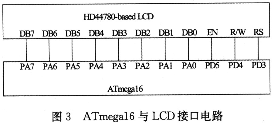
The data bus DB7~DB0 of the HD44780 is connected to PA7~PA0 of ATmega16, and RS, R/W and EN are respectively connected to PD3, PD4 and PD5 of the single chip microcomputer. Use the I/O port of the ATmega16 to control the LCD for command and data input, and correctly display the latitude and longitude data.
2 Interface programming of ATmega16 and M12 modules The system uses the serial port of ATmega16 to issue control commands and receive positioning information to the M12 module. M12 module support. Two data output modes, Motorola binary format and NMEA0183 format. In Motorola binary mode, M12 outputs data and receives instructions at 9600 bps; in NMEA 0183, M12 outputs data and receives instructions at 4800 bps. By default, the M12 module works in Motorola binary mode. In order to obtain higher data transmission speed, the default working mode of the M12 module is used here, namely the Motorola binary mode. In this mode, the serial data transfer format is: 8-bit data bits, 1-bit stop bit, no parity and hardware flow control.
ATmega16 controls it by sending an AT command to M12. Motorola has a total of 69 AT I/O commands, of which 51 are supported by the M12 module. With these instructions, it is convenient to perform date and time setting, custom coordinate setting and positioning information reading for the M12 module. In this system, only the positioning information of the M12 module needs to be read, so only one of the 51 instructions is used in the program:
@@EqmC
This command is used to control the output positioning information of the M12 module. Where "@@" is the prefix of the I/O instruction; "Eq" is the keyword of the instruction; "m" is the M12 module output (response) information mode selection, and its value can be an integer between 0 and 255, when " When m" is 0, the response information is only output once. When "m" is 1, the response information is output once every second. When "m" is 2, the response information is output every 2 s, and so on, when "m" "When 255, the response information is output every 255 s; "C" is the checksum data of the instruction;"
The M12 module can only accept commands entered in Motorola binary form by default. The so-called Motorola binary form refers to the binary instruction code that combines the prefix of the instruction, the keyword and the suffix (carriage return and line feed) into the corresponding ASCII code, and the combination of the mode "m" and the checksum "C". Used in the system 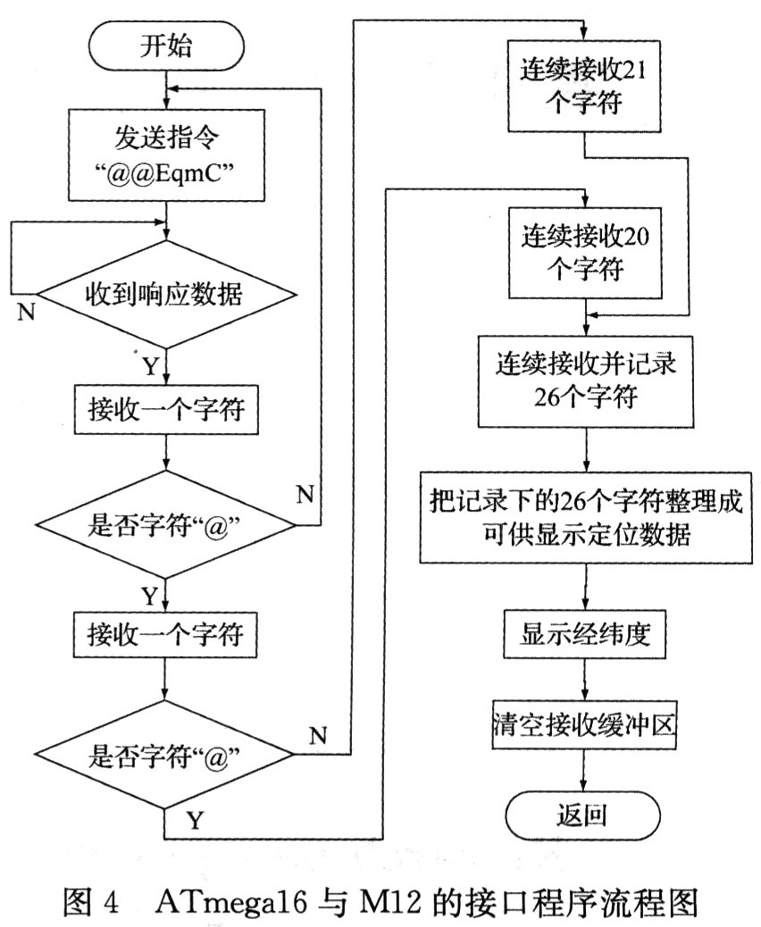
ATmega16 first requests the M12 module to output positioning data (issue the command "@@EqmC" to the M12 module), and then waits for the M12 module to send back the data. When the M12 module sends back the data, ATmega16 first makes a judgment to confirm that it receives the expected positioning information, and then intercepts the positioning information (latitude and longitude data), and arranges the data to display the latitude and longitude data on the LCD after being displayed. Finally, the receiving buffer of the serial port is cleared to avoid an error when receiving the information next time. Since the M12 module can only respond to one instruction within 1 s, the receiver's data information is updated once every 1 s.
3 Positioning Accuracy Test In order to test the positioning accuracy of the M12 module, the GPS reference point (coordinate: east longitude 113°20.538541', north latitude 23°09.581834') was tested at the geotechnical laboratory of the Engineering College of South China Agricultural University. The PC is connected to the M12 development board for latitude and longitude data acquisition, and it runs continuously for about 50 minutes, and collects 3125 sets of latitude and longitude data. Through the analysis of the measured data, the static positioning error of the M12 module is ≤7.81 m, which is in line with the accuracy range of <25 m under the SA-free policy marked in the user manual.
4 Conclusion From the perspective of cost reduction, the GPS latitude and longitude data system based on ATmega 16 uses single-machine static positioning technology for geolocation. This positioning technology is not high-precision, but it is easy to popularize and can be used in the field of general civil geolocation. The system is also used in the field of professional positioning navigation by replacing GPS modules with higher precision or using differential positioning technology to improve positioning accuracy.
28mm DC Planetary Gear Motor includes 28RP385 and 28RP395 DC Planetary Gear Motor. Some customer has a higher requirements about the motor performace, we can also use 28RP3161 and 28RP3175 Dc Planetary Gear Motor. This kind of Planetary Gear Motor is mainly applied on medical devices like injection equipment, beauty instruments and massage devices.
28Mm Dc Planetary Gear Motor has the following characterics:
1.the 28mm dc Planetary Gear motor has a good performance on the noise level;
2.the planetary gearbox has a longer working life than other types gearbox;
3.the micro dc planetary gear motor has a small size, but the torque it could reach equal to some gearbox over 30mm

For 28mm dc planetary gear motor, there are 4 types gearbox;
For the 1 stage gearbox, we have 3.7, 5.2 gear ratio;
For the 2 stages gearbox, we have 14, 19, 27 gear ratios;
For the 3 stages gearbox, we have 51, 71, 100, 139 gear ratios;
For the 4 stages gearbox, we have 186, 264, 369, 515, 721 gear ratios;
| Number of stages | 1 | 2 | 3 | 4 |
| Reduction ratio | 3.7, 5.2 | 14, 19, 27 | 51, 71, 100, 139 | 186, 264, 369, 515, 721 |
| Gearbox length(L) mm | 27.5 | 35.5 | 43.5 | 51.5 |
| Breaking torque(kgfcm) | 6 | 10 | 20 | 40 |
| Gearbox efficiency | 90% | 81% | 73% | 65% |

28mm DC Planetary Gear Motor
28Mm Dc Planetary Gear Motor,28Mm Brushless Dc Motor,28Mm Planetary Gear,28Mm Planetary Gear Motor
SHENZHEN DONGMING MOTOR CO., LTD. , http://www.dmdcmotor.com