Aiming at the problem of low GPS positioning accuracy and poor anti-shadowing in the current train locomotive monitoring system, a combined navigation and positioning design scheme based on GPS, ADXRS150 micro silicon gyroscope and locomotive speed sensor is proposed, and a combined navigation information fusion algorithm model is established. The experimental result data is given.
This article refers to the address: http://
In the actual application, the locomotive pit stop is accurately judged, the positioning accuracy is improved, and the reliable position data is provided for the remote monitoring of the locomotive.
Since 1997, China's railways have carried out five major speed-ups. The speed-increasing network has basically covered the major regions of the country. The top speed of express trains has increased from 120 kilometers to 160-200 kilometers. As the running speed of the locomotive increases, the requirements for safety and reliability are also correspondingly improved. This requires simultaneous system transformation, enhanced monitoring measures, and safe operation. Traffic safety monitoring is an important part of the railway informationization overall planning application system and an important technical means to improve the railway transportation safety and security capabilities. The application of integrated navigation and positioning technology in the locomotive safety monitoring system can solve the problem of low single-GPS positioning accuracy and poor anti-shadowing [1], realizing accurate positioning of locomotive running trajectory and accurate judgment of the inbound orbit, and driving safety monitoring system. Provide reliable operational data.
1 Design principle of locomotive integrated navigation positioning terminal
The locomotive integrated navigation positioning terminal requires fusion processing of GPS information, gyroscope information, and locomotive speed sensing information, and transmits the fused processed information to the monitoring center through the GPRS wireless network. At the same time, large-capacity flash memory is used locally to save some characteristic parameters of the track line, and the feature parameters can be automatically updated by wireless to ensure the real-time performance of the track characteristic parameters. The terminal performs a fusion process on the collected various state information, and compares with the track feature parameters to issue various prompt signals. The terminal schematic is shown in Figure 1.
The system main control CPU is LPC2138, the CPU is ARM7 core [2], which is responsible for the fusion processing of various information; the GPS module uses GARMIN15 engine board, in the case of positioning, it is used to obtain the longitude, latitude and altitude of the location of the locomotive. Information; ADXRS150 micro silicon gyroscope for obtaining angular velocity information of the locomotive. The AD574 is a 12-bit A/D converter chip that samples and quantizes the analog angular velocity signal output from the ADXRS150 micro silicon gyroscope. The Samsung K9F5608 Flash is used to store some of the characteristic parameters of the track. The power management module input is 110V DC power supply. It is a 12V, 5V, 3.3V voltage, providing a stable power supply for the normal operation of each module.
2 Analysis and processing of combined positioning information
2.1 GPS positioning information
GARMIN15 GPS engine board positioning accuracy <15 meters (no interference), the output data format is NMEA0183. The format contains a variety of statements, of which GPRMC is the most commonly used statement, which describes the longitude, latitude, time, altitude, and current speed of the location. The specific statement format is: $GPRMC, <1>, <2>, <3>, <4>, <5>, <6>, <7>, <8>, <9>, <10>, < 11>, <12>? é„¢hh. The GPS engine board outputs data once every 1 second through the serial port, and its serial port baud rate is 9600 bps. GPS provides very accurate time information in the case of positioning.
2.2 Locomotive speed sensing information
At present, the safety driving recorder equipped on the locomotive outputs the relevant locomotive status information, including the locomotive speed information, every 20~40ms through the RS485 bus at a transmission rate of 28 800 bps. Since the information transmission is very frequent, in the design process, a separate MCU is used to collect and process the information, and the main control CPU periodically acquires the speed state information of the locomotive through the I2C bus, thereby greatly reducing the workload of the main control CPU. The application of locomotive speed sensing information in a short period of time is relatively accurate, but in the long run, due to the existence of accumulated errors, it will bring great deviation.
2.3 ADXRS150 micro silicon gyroscope information
The ADXRS150 is a MEMS angular velocity sensor with an angular velocity range of 150°/s integrated on a tiny chip. Accurate reference voltage and temperature output compensation technology, 7mm × 7mm × 3mm micro-volume package [3]. In the actual use of the ADXRS150 micro silicon gyroscope, in order to obtain stable and reliable angular velocity information, the following aspects need to be properly solved:
(1) Filter
During the running of the locomotive, the angular velocity changes slowly, so the passband cutoff frequency of the low-pass filter can be set lower, which can eliminate the influence of some high-frequency components. The passband cutoff frequency of the low pass filter can be calculated by:
![]()
Among them: Rout=180kλ, which has been integrated in the ADXRS150 micro silicon gyroscope, combined with the actual running condition of the locomotive [4], external Cout=47nF.
(2) Zero drift
During the operation of the ADXRS150 micro silicon gyroscope, the center zero will drift with time, so the zero point needs to be accurately corrected [5]. By determining the GPS information and the locomotive speed sensing information, it can be determined whether the locomotive is at a standstill. Once the locomotive is at a standstill, the zero calibration procedure is initiated to determine the zero analog voltage, and during the actual operation, the zero offset can be eliminated.
2.4 Data fusion processing
(1) Positioning packet structure
#UTPM, <time>, <longitude>, <latitude>,, <locomotive speed>, <gyro angular velocity>, <inertial navigation time>, <state and judgment condition>,
(2) Position information processing under GPS positioning
According to the state and the judgment condition, it can be judged whether the current GPS is positioned, and in the case of confirming the GPS positioning, the longitude and latitude information in the data packet is valid.
(3) Position information processing when GPS is not positioned
In the case that the GPS is not positioned, the inertial navigation will be started, and the running speed will be calculated by applying the locomotive speed sensing information. Set the sampling time interval of the locomotive speed information to Tavr, and the running speed at time i is vi, then the running mileage is:

The position of the inertial navigation starting point is marked by longitude and latitude. Since the track longitude and latitude information are saved locally, combined with the railway kilometer, S can be directly converted into longitude and latitude information. At the same time, the monitoring center can also process and display the data in combination with the track electronic map.
(4) Orbital judgment
When the locomotive enters the station, the GPS signal may be affected by the occlusion. Even if the GPS works normally, it is difficult to judge the locomotive track because the track spacing is relatively small. Therefore, it is necessary to obtain the orbital radiance data through the gyroscope. According to the relationship between the arc and the angular velocity:
![]()
In the period from t1 to t2, the total radians are calculated as:
![]()
If the sampling interval of the gyroscope is T, then the piecewise linearization is used to calculate the integral:

Where n is the angular velocity at time t2 and m is the angular velocity at time t1. (mn)T is the length of the summation time, and the length of the summation time is intelligently adjusted according to the orbital parameters. In the Flash of the terminal, the track line parameters (including the arc information at the switch) have been saved, and the calculated θ1 and the arc information at the turnout are compared to determine the specific track into which the locomotive enters.
3 test data and results analysis
The ADXRS150 micro silicon gyroscope output angular velocity signal is converted to radians after A/D conversion. The positive sign in front of it represents clockwise rotation and the negative sign represents counterclockwise rotation. Based on the orbital parameters of the current location, the track of the locomotive is judged and compared with the GPS azimuth.
The test position is: north latitude 22 degrees 57 minutes 4728 seconds, east longitude 108 degrees 21 minutes 0413 seconds, the current locomotive speed is 49.5km / h, the data is analyzed when the locomotive crosses the turnout time, as shown in Figure 2, Figure 3.
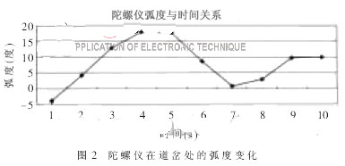
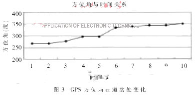
The test data shows that the locomotive rotates clockwise at the position, and by querying the data in the local flash, the locomotive is selected at the track.
The combination positioning technology based on GPS, gyroscope and locomotive speed sensor solves the defect of single GPS positioning, improves the positioning accuracy, and accurately judges the locomotive arrival track by combining the central electronic map. In the test and trial run, significant results have been achieved, providing reliable track position data for real-time monitoring and safety warning of the locomotive.
Communication Cables,Audio Cable ,Ethernet Cables ,Communication Wire
Electric Wire & Cable Co., Ltd. , http://www.nbpowercable.com