In the design of electronic devices, rotary encoder switches are commonly used. These components, also known as digital potentiometers, allow users to adjust settings by rotating and pressing. The English term for this is "Rotary Encoder Switch." Before writing the driver code for this component, I did some research online using Google and Baidu, and found that it has three main functions: left rotation, right rotation, and a press action. It typically has five pins, and its physical appearance is shown below:

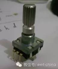

Here are some basic wiring tips: (1) Pins 1 and 3 should be connected to pull-up resistors, usually 10kΩ is sufficient; (2) Pin 2 is generally connected to ground; (3) Pins 4 and 5 are used for the switch contact of the bottom button (when pressed, pin 4 goes low). The wiring diagram I used during debugging is as follows:

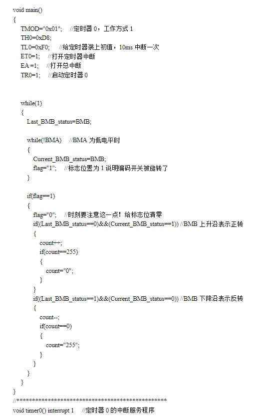
In reality, it's not too difficult to use. However, I've noticed that many online resources suggest it can be tricky to determine the direction of rotation. In my opinion, this is more of a misconception. After reading my code, you'll see that it's actually quite straightforward. The key to determining the direction is observing the edge of signal BMB when BMA is low. A rising edge indicates clockwise rotation, while a falling edge indicates counter-clockwise. With clear code, the device can operate smoothly and reliably.
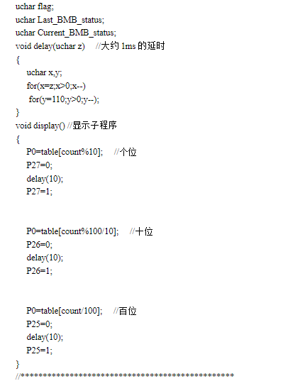
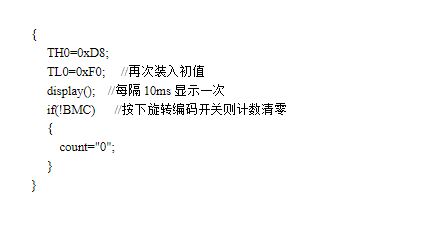
Without further delay, here is the code:
#include <reg52.h>

#define uchar unsigned char
#define uint unsigned int

sbit BMA = P1^4;
sbit BMB = P1^5;
sbit BMC = P1^6;
sbit P27 = P2^7;
sbit P26 = P2^6;
sbit P25 = P2^5;

uchar code table[] = {0xC0, 0xF9, 0xA4, 0xB0, 0x99, 0x92, 0x82, 0xF8, 0x80, 0x90};
uchar count = 0;

void delay(uint ms) {
    uint i, j;
    for(i = ms; i > 0; i--)
        for(j = 110; j > 0; j--);
}

void main() {
    while(1) {
        if(BMA == 0 && BMB == 1) {
            count++;
            if(count > 9) count = 0;
        } else if(BMA == 0 && BMB == 0) {
            count--;
            if(count > 9) count = 0;
        }
        P2 = table[count];
        delay(100);
    }
}
The images below show the physical structure and the code logic in detail:
Corrugated Flexible Conduit,Split Flexible Electrical Tubing,Corrugated Tube,Corrugated Hose
Dongguan Liansi Electronics Co.,Ltd , https://www.liansisleeve.com