Double voltage rectifier circuit working principle - News - Global IC Trade Starts Here Free Join
Double voltage rectification circuits are widely used in power supply systems to achieve higher output voltages using capacitors and diodes. This type of circuit takes advantage of the energy storage capability of capacitors, allowing the output voltage to be several times the secondary voltage of the transformer. The basic concept is known as a voltage doubler circuit.
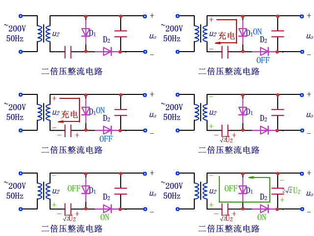
The working principle of a voltage doubler circuit can be better understood through its operation during each half-cycle of the AC input. When the secondary voltage (u2) is positive, diode D1 becomes forward-biased, allowing capacitor C1 to charge up to the peak voltage of the secondary winding. At the same time, diode D2 remains off, isolating the second stage.
During the negative half-cycle of u2, the polarity reverses. Diode D2 turns on, while D1 turns off. This allows capacitor C2 to charge, again reaching the peak voltage. As a result, the output voltage across C2 is approximately twice the peak voltage of the secondary winding. This process repeats with every cycle, effectively doubling the voltage.

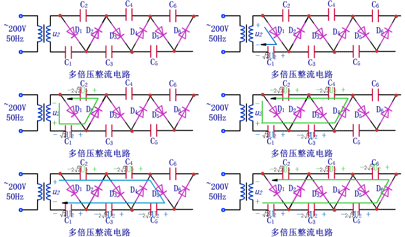
This principle can be extended to create multi-voltage rectifier circuits, where more stages are added to multiply the output voltage even further. For example, by adding additional capacitors and diodes, it's possible to generate 3x, 4x, or even higher voltages depending on the design.
Consider the multi-voltage rectifier circuit shown below. In this configuration, multiple capacitors are charged sequentially during different parts of the AC cycle. Each capacitor stores a portion of the voltage, and when combined, they produce a much higher output. For instance, if C1 charges to V, then C2 to another V, and so on, the total output could reach 2V, 3V, or more.

By selecting the right combination of capacitors and diodes, engineers can tailor the output voltage to meet specific requirements. These circuits are commonly used in applications such as high-voltage power supplies, signal processing, and specialized electronic devices where standard transformers may not provide sufficient voltage levels.
Understanding how these circuits work helps in designing efficient and reliable power solutions. Whether you're building a simple voltage doubler or a complex multi-stage rectifier, the key lies in controlling the charging and discharging of capacitors to achieve the desired output voltage efficiently.
Ceramic Parts,Advanced 95 Ceramic Materials,High Strength Ceramics,Durable Ceramic Components
Yixing Guanming Special Ceramic Technology Co., Ltd , https://www.guanmingceramic.com