The design uses STM32 single-chip microcomputer as the controller, and the temperature single feedback control system is designed to control the temperature of the water in the electric water heater. The water temperature signal is collected by the PT100 temperature sensor, and the water temperature signal is processed by the analog forward channel. The STM32 single-chip microcomputer is used to control the output PWM signal, and the signal is used to control the contactor to control the power supply of the electric water heater, and finally realize the control of the water temperature. At the same time, the monitoring interface is designed by the configuration software to realize the control display of the water temperature. Through the design of this subject, the automation students can have a further understanding of industrial process control objects, and at the same time master the design process of the automation control system, laying a solid foundation for future work and study.
First, the control system hardware design1. Overall design of control system hardware
Temperature is a very important variable that needs to be accurately controlled. Temperature control systems are often used to keep the temperature constant or to vary the temperature according to certain regulations. Closed loop control is the most common type of temperature control system. This design is a closed loop temperature control system. The closed loop temperature control block diagram is shown in Figure 1.
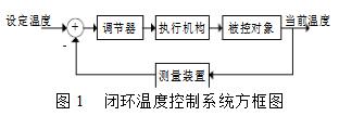
The temperature control system consists of the controlled object, the measuring device, the regulator and the actuator. The measuring device measures the water temperature in the controlled electric water heater, and the controller compares the measured value with the given value. If there is a deviation, the controller processes the deviation signal, and outputs a control signal to the actuator to start or stop the electric addition. The water heater works and finally adjusts the temperature to the set value. The controlled object is the temperature of the water in the electric water heater.
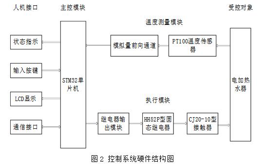
Based on the above theory, the control system is designed. The hardware of the system mainly includes: STM32 single chip microcomputer, PT100 temperature sensor, switching power supply, analog forward channel, relay output module, HH52P solid state relay, CJ20-10 contactor, electric water heater The hardware structure of the control system is shown in Figure 2.
2, STM32 microcontroller introduction
The STM32 microcontroller is the heart of the entire temperature control system. Because of the high requirements for temperature controllers, such as high execution speed, high control accuracy, high stability and high sensitivity, it is inevitable to choose a microcontroller with high performance and economy. This design selects STM32F103VET6 MCU belonging to STM32 series as the core component of the control circuit. The MCU belongs to the 32-bit high-performance, low-cost, low-power enhanced series MCU produced by ST STMicroelectronics. Its core is ARM. The company's newly developed Cortex-M3 architecture is designed to meet the high performance, low power consumption and economical requirements of users. The enhancement of the architecture of the ARM Cortex-M3 processor makes the STM32 enhanced series of microcontrollers endless, and its THUMB-2 instruction set makes its instructions more efficient and more powerful.
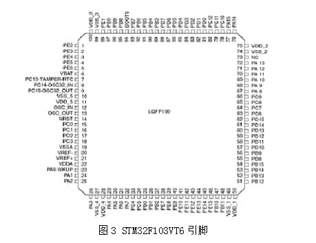
STM32F103VET6 uses a thin quad flat package technology (LQFP) with 100 pins, on-chip 512KB FLASH, 64KB RAM (on-chip 12Bit A/D, D/A, PWM, CAN, USB, secure digital I/O card SDIO , variable static storage controller FSMC and other resources). A serial peripheral interface (SPI) bus controlled M25P16 (16MB capacity serial FLASH) for storing data, code, fonts and graphics. A 2.8-inch 260,000-color display (TFT 240X320 (with touch screen)) interface, using the MCU's FSMC 16-bit data interface mode, the touch screen uses ADS7843 (4-wire resistive touch screen conversion interface chip) chip with hard SPI interface control. STM32 MCU uses a supply voltage of 2.0~3.6V, and can work in the temperature range of -40°C~85°C. The highest operating frequency is 72MHz. The pin distribution is shown in Figure 3.
The STM32F103VET6 microcontroller has three different clock sources to choose from to drive the system clock, the HIS oscillator clock, the HSE oscillator clock, and the PLL clock. These devices also have two secondary clock sources, a 40KHz low-speed internal RC and a 32.768KHz low-speed external clock source that can be used to drive the watchdog clock and RTC. Any clock source can be turned off or on independently when not in use to optimize system power consumption.
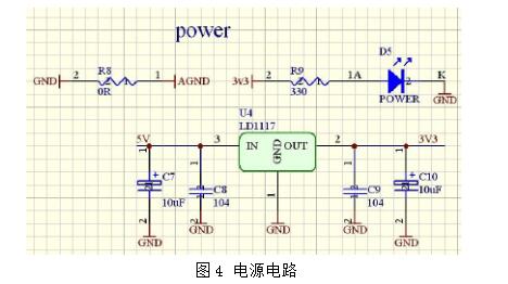
The MCU is powered by the AMS1117-3.3 chip circuit. The input is +5V, which provides a fixed voltage output of 3.3V. In order to reduce the electromagnetic interference, the C7-C10 filter is required to supply power to the CPU. R8 is the connection resistance of DGND and AGND, R9 and D5. The LED and power supply indicate the connection resistance, and the power supply circuit is shown in Figure 4.
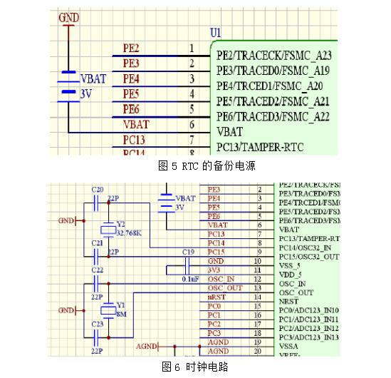
The RTC backup power supply uses a VBAT 3.3V lithium ion chip battery, and the RTC backup power supply is shown in Figure 5.
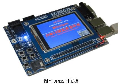
The external crystal/ceramic resonator (HSE) (P12, P13) of the single chip microcomputer, Y1 is an 8MHz crystal resonator, C22 and C23 are resonant capacitors, and the size is 22P. The system clock is clocked up to 72MHz via the PLL module. The low-speed external clock source (LSE) (P8, P9) of the microcontroller, Y2 is a 32.768KHz crystal resonator, and the C20 and C21 resonant capacitors are 22PF. It should be noted that according to the recommendation of ST company, Y2 should use a crystal oscillator with a capacitive load of 6PF. Otherwise, there may be a phenomenon of vibration stoppage. The clock circuit is shown in Figure 6.
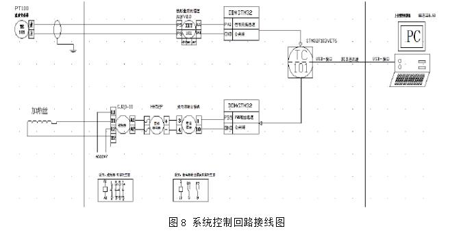
At present, STM32 MCU has been applied in many occasions, and has developed many excellent products, such as programmable logic controllers, printers, scanners, motor control and some digital products. STM32 has become a very mature applicable control device. The development board selected for this design is shown in Figure 7.
3, hardware wiring and its principle introduction
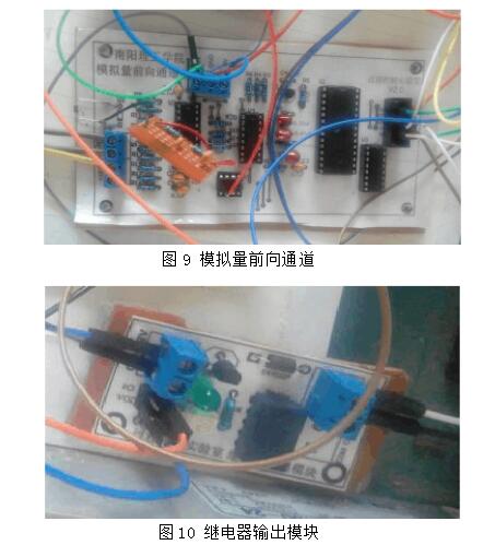
When the temperature control system is in normal operation, the PT100 temperature sensor first detects the current temperature signal of the water in the controlled object and the water in the water heater, and changes the resistance value of the PT100 temperature sensor in the analog forward channel for conversion amplification and cold junction temperature. Compensation, linearization. Then, the analog voltage signal output from the analog forward channel is sent to the STM32 MCU of the main control module for processing, and is digitized and compared with the digital value of the given temperature value. The MCU processes the data according to a predetermined PID control algorithm, and displays the current temperature and the set value through the display screen. The program automatically determines whether the system has an abnormality. If the system is running normally, the PID operation result is used as the output control amount to control the output of the PWM waveform. The action of the actuator is controlled to achieve the purpose of turning on or off the main circuit of the resistance furnace to realize the control of the electric water heater. When the MCU controls the water temperature, it can choose to connect to the host computer for configuration monitoring, transfer the variable information to the host computer, and download the parameters set by the host computer to the controller STM32, so as to achieve the effect that the host computer configuration should have. The design system control loop wiring is shown in Figure 8.
The analog forward channel uses TI's TLC7135 (also known as ICL7135) chip, plus the special processing of the preamplifier analog op amp, and some other basic components to successfully achieve the measurement of weak signals. TLC7135 has the following characteristics: high input impedance, almost no influence on the circuit under test; automatic zero calibration; accurate differential input circuit; automatic discrimination of signal polarity; over- and under-voltage output signals; bit scanning (5 bits in total) ) Output with BCD code. This design uses PT100 as the temperature sensor. It needs to connect three signal lines. The two lines are internally shorted. After the signal is strobed by the single 8-channel digital control analog electronic switch CD4051, the analog voltage value corresponding to the temperature signal is obtained after the operational amplifier. The processing method of this design selection is to draw the analog voltage signal through the 6-pin of the operational amplifier, and directly realize the digital processing by the single-chip microcomputer. The analog forward channel is shown in Fig. 9 [6].
The relay output module is mainly used to execute the PWM control signal of the STM32 output, and the solid state relay HH52P and the AC contactor CJ20-10 are turned on or off in time to realize the control of the main circuit of the heater. Since the PWM signal output from the single-chip microcomputer is low at a voltage of about 3.3V, it cannot be directly used to drive the 24V solid-state relay HH52P. Therefore, it is necessary to add a relay output module in the middle. The relay output module supply voltage is 12V, and the coil can be controlled as long as there is an input signal. The pull-in and off, relay output module is shown in Figure 10.
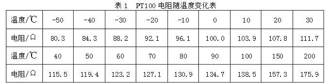
PT100 is a platinum thermal resistor whose resistance changes with temperature. A 100 after PT means that it has a resistance of 100 ohms at 0 ° C and a resistance of about 138.5 ohms at 100 ° C. Common PT100 temperature sensing elements are ceramic components, glass components, mica components, which are processed by a complex process of platinum wire wound around a ceramic skeleton, a glass skeleton, and a mica skeleton [7]. The working principle of PT100: When the PT100 is at 0 °C, its resistance is 100 ohms, and its resistance will increase approximately evenly with the temperature rise. But the relationship between them is not a simple proportional relationship, but should be closer to a parabola.
The formula for calculating the resistance of the platinum resistance as a function of temperature is as shown in equations (1) and (2).
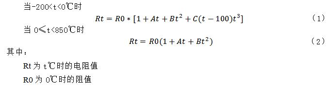
The A, B, and coefficient in the formula are experimentally determined. The RT curve of the PT100 platinum resistance is shown in Figure 11.
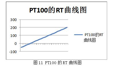
Table PT100 resistance change with temperature is shown in Table 1.
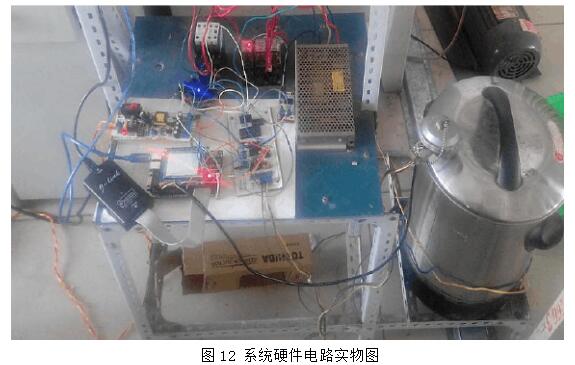
The physical diagram of the system hardware circuit of this design is shown in Figure 12.

1. Software development environment and its tools
C language programming
C language is a computer programming language. It has both high-level language features and assembly language features. It can be used as a system design language to write a working system application, or as an application design language, to write an application that does not depend on computer hardware. Therefore, it has a wide range of applications, and C programming language is widely used at home and abroad. The computer programming language used. C is a structured language with a clear hierarchy that facilitates the organization of programs in a modular fashion that is easy to debug and maintain. C language has been widely used as a high-level programming language. The software program written in C language is not specific to a specific hardware system. It can be transplanted according to different single-chip microcomputers. Based on the above features and advantages of C language, this design Software programming, using C programming language [9].
Introduction to software development tools
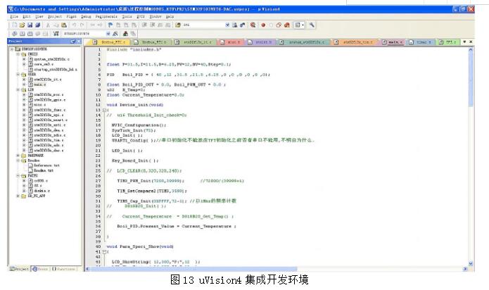
The programming software uses RealView MDK from Keil, Germany. This programming software is validated and used by more than 100,000 embedded engineers or scholars around the world. It is ARM's latest software development tool for various embedded processors. It integrates the industry's most advanced technology and combines the features and functions required by most software engineers in China. The uVision4 integrated development environment supports ARM7, ARM9 and the latest Cortex-M3 core processor, automatically configures boot code, and integrates Flash with fewer modules. , powerful performance analysis capabilities. Its integrated development environment is shown in Figure 13.
The main performance of the uVision4 integrated development environment:
(1) The source code editor is very powerful.
(2) The device database can be configured according to the development tools.
(3) The Project Manager can be used to create and maintain projects.
(4) Compile tool set assembly, compilation, and connection process in one.
(5) A dialog for setting up the development tool configuration.
(6) A source-level debugger that truly integrates high-speed CPU and on-chip peripheral emulators.
(7) Advanced GDI interface for software debugging of target hardware and connection of ULINK2 emulator.
(8) Flash programmer for downloading applications to the Flash ROM.
(9) Complete development tool manual, equipment data sheet and user guide.
2, STM32 project creation and configuration
After learning the programming of the software, I have a preliminary understanding of the STM32 program. The following is the whole process of creating and configuring the project.
(1) Create a new folder (each project compiled in the future will be placed in this folder, name it yourself, all files here can be named by themselves, for example: STM32 file). The library function version used here is the V3.5 library function version.
(2) Create a folder (name can be named according to the program you wrote, such as: Demo). Create a new subfolder User for storing user source programs. Create a new subfolder Project, user KEIL project file. Create Obj and List subfolders under Project to store the intermediate files generated during the compilation process. Copy the main.cstm32f10x_conf.h, stm32f10x_it.c, stm32f10x_it.h, system_stm32f10x.c and other files to the User file.
(3) Copy the source code to the Demo folder.
Copy the stm32f10x_stdperiph_lib3.5 / Libraries folder as a whole to the Demo folder. This is the ST standard library, provided in source code form. You can also copy the Libraries folder directly into the STM32 file folder so that it is in the same directory as other projects created in the future, so that the projects in that directory can share Libraries. You don't have to copy a Libraries once you've created a project.
(4) Create a new Keil MDK project
ï¬ Start Keil MDK, click on the menu New uVision Project, and follow the wizard. Select the CPU type as STM32F103VE. Select No when prompted to copy the startup code. In order to extend the life of the chip and speed up the simulation, you can directly simulate in ram (ram simulation speed is fast), use ram simulation to lose all data after power off, modify Target name, add two, one Flash, one Ram.
ï¬ In order to facilitate code management, create several groups under this Project, User: store the source code written by the user; RVMDK: store the startup file (assembly file); StdPeriph_Driver: store the ST standard library file; CMSIS: store the CMSIS interface file ( This is also part of the library; after creating the group, we start adding files one by one. Add User: add mainframe: main.c stm32f 10x_it.c add RVMDK: statup_stm32f 10x_hd.x; add StdPeriph_Driver: we use STM32 temperature control system design
Some .C files. Such as: misc.c stm32f 10x_rcc.c stm32f 10x_gpio.c, etc.; add CMSIS: core_cm3.c system_stm32f 10x.c.
(5) Configure the project and click the “OpTIons†button.
ï¬ Open Flash to adjust the Flash settings, switch to Output, then select the Object folder, check the CreateHex File and change the Name Executable to output.
Switch to LisTIng and select the LisTIngs folder. Switch to C/C++, add two precompiled macros STM32F10X_HD, USE_STDPERIPH_DRIVER (this is the ST library used in these two macros), modify the Includes path. Switch to Debug, select the hardware debugger, we select ST-Link Debugger and check the Run to main. Switch to Utilities, select the debugger type, and we choose ST-Link Debugger.
ï¬ Open Ram and adjust the Ram settings. Switch to target and switch to Output. Select the Object folder and check the Create Hex File. Change the Name Executable to output. Switch to Listing and select the Listings folder. Switch to C/C++, select One ELF Section per Function, add two pre-compiled macros STM32F10X_HD, USE_STDPERIPH_DRIVER (this is the ST library used these two macros), modify the Includes path. This will create a new project, we can edit the program according to the function you want to achieve.
Features
â—† Wide Application
Specialized in Hairdryer Switch with crisp handfeel,clear gears,reliable electrical contact
â—† Easy to install and use
Simple installation, freely turn on or off the load which you want to control.
â—† High Operating Life
Made of high quality polyamide eP(Nylon PA66) material, this sturdy mini boat Rocker Switch is born for anti-corrosion,anti-acid and high resistant with silver terminals.100,000 times of ON/OFF operating life span.
Automotive Rocker Switch,Dual Rocker Switch,Red Rocker Switch,Custom Automotive Rocker Switches
Ningbo Jialin Electronics Co.,Ltd , https://www.donghai-switch.com