Xilinx Programmable Logic Device Design and Development (Basic) Serial 9: Spartan
The file extension of the ChipScope Pro kernel inserter is called cdc. A new cdc program can be created in the ISE project, or the kernel inserter can be activated in the implementation process.
Note: Before using the kernel inserter, be aware of the property settings of some engineering projects.
(1) If the XST synthesis tool is used, set the [Keep Hierarchy] property to [Yes] or [Soft] to disable the XST tool from optimizing the design, retaining the original design level, and retaining the NET network node name. The setting method is as follows.
Select [Edit] → [Preferences] to open the properties dialog.
Select the [Processes] page.
Set the attribute display drop-down box to [Advanced] and click [OK].
Right-click [Synthesize] and select the [ProperTIes] option.
Set the [Keep Hierarchy] property to [Yes] or [Soft] and click [OK].
(2) Set the bitstream generation options correctly.
In the Project Navigator, click the [Generate Programming File] right button and select the [ProperTIes] option.
Select the [Startup opTIons] page.
Select the [FPGA Start-Up Clock] drop-down box and the JTAG Clock starts the clock.
Next, it introduces how to call ChipScope's kernel inserter (Core Inserter) in the ISE environment, as well as the meaning of the various parameters of the kernel inserter and how to configure it.
1. Run ISE 11.1 to open the design project.
2. Create a CDC file. Under the ISE 11.1 interface, there are two ways to create a CDC file:
Click [Project] → [New Source] to pop up the source settings interface, select [ChipScope DefiniTIon and Connection File], enter the file name, as shown in Figure 9-28. Click [Next] to generate and configure the kernel according to the default settings until [Finish] generates a .cdc file.
Note: [ChipScope Definition and Connection File] can be displayed in [New Source] of ISE 11.1 only if ChipScope Pro 11.1 is installed.
![[New Source Wizard] source program type selection interface](http://i.bosscdn.com/blog/0I/34/0c/03_0.png)
Figure 9-28 [New Source Wizard] source program type selection interface
Select [Project] → [Add Source] ([Add Copy of Source]) and select the existing .cdc file.
3. ChipScope kernel inserter properties and parameter settings.
(1) In the [Sources in Project] window, double-click the cdc file. The kernel inserter interface that pops up is shown in Figure 9-29. Set the parameters of the Chipscope Pro.
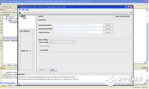
Figure 9-29 Kernel Inserter User Interface
The menu items in the menu bar and their functions are:
[File] menu: Contains common file operation commands, such as [Open Project], [Save], [Save As]. [Refresh Netlist] is used to manually update the netlist.
[Edit] menu: including creating a new integrated logic analysis unit [New ILA Unit], or creating a new ATC2 unit [New ATC2 Unit], delete unit [Remove Unit], and parameter settings [Preferences] and other commands.
[Insert] menu: Contains the [Insert Core.] command. When the parameters of the ILA Core are set, you can use this command to insert the netlist of the integrated logic analyzer into the netlist of the original design.
[Design Files] Design file option group, there are several options:
Specify the netlist of the input design. Click [Browse], select the directory where the input design is located, and modify the output design netlist and output directory. (If the core inserter is activated in ISE, enter the netlist and output netlist, directory, device model, etc. The parameters are automatically filled in. In this case, these parameters can only be modified in the ISE project properties and not modified in the kernel inserter.)
Engineering parameters[Device Setting] Device setting option group:
[Device Family]: Select the target FPGA device family, and the kernel generator will generate the ICON and capture kernel optimized for the device.
[Use SRL16s]: Used to control whether to generate the kernel with SRL16 and SRL16E logic. If this option is not selected, it will be replaced by a trigger and a multiplexer, which affects the size and performance of the generated core. The default setting is Enabled.
[Use RPMs]: Used to control whether a separate kernel is generated with related layout macros (RPMs). This check box prevents the place-router from optimizing the layout of the logic of the ChipScope Pro kernel in the area. If the design takes up most of the logical resources, these layout restrictions may not be met.
[Core Utilization] Option Group: On the left side of the kernel generator is the kernel resource utilization display window, which lists the ChipScope core resource utilization inserted in the design netlist, including lookup table (LUT), flip-flop (FF) and block RAM (BRAM). ).
Note: Only the Spartan-3, Spartan-3E, Spartan-3A, Spartan-3A DSP, and Virtex-4 device families display the ChipScope core resource utilization feature.
(2) ICON core configuration option settings. Click [Next] in Figure 9-29 to bring up the ICON core configuration option setting interface, as shown in Figure 9-30.
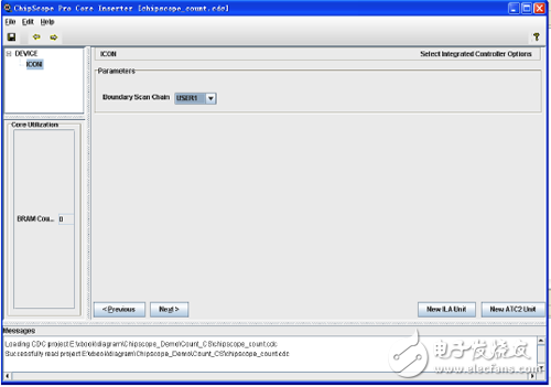
Figure 9-30 ICON core configuration option interface
[Boundary Scan Chain] drop-down selection box: Boundary scan chain, the analyzer can communicate with the ChipScope kernel through the USER1, USER2, USER3 or USER4 boundary scan chain. (This option is not supported on Spartan-3, Spartan-3E, Spartan-3A or Spartan-3A DSP devices.)
The BUFG insertion can be disabled.
Open the [Edit] menu → [Preferences] property, and pop up the [Edit Preferences] property editing dialog window, as shown in Figure 9-31.
Enable JTAG global clock buffer control: In the [Miscellaneous] tab, select the [Show Manual JTAG Global Clock Buffer Control in ICON Panel] check box.
Disable BUFG on JTAG clock: [Put JTAG Clock on a Global Clock Buffer] check box is not selected.
![[Edit Preferences] interface](http://i.bosscdn.com/blog/0I/24/3S/54_0.png)
Figure 9-31 [Edit Preferences] interface
(3) Click [New ILA Unit] in Figure 9-30 to pop up the ILA trigger option and parameter setting interface, as shown in Figure 9-32.
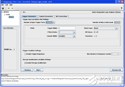
Figure 9-32 ILA trigger option and parameter setting interface
Trigger Parameters tab:
Trigger Input and Match Unit Settings option group:
BNC Female Bulkhead Waterproof Connector,Bulkhead BNC Connector,BNC Bulkhead Connector Female,BNC Compression Connector
Xi'an KNT Scien-tech Co., Ltd , https://www.honorconnector.com