Introduction COB (Chip-on-Board) packaging technology has received more and more attention in the industry due to its low thermal resistance, high luminous flux density, small color tolerance and few assembly processes. COB packaging technology has been used in IC integrated circuits for many years, but for the majority of luminaire manufacturers and consumers, LED light source is COB package or novel technology.
The reliability of LED products is closely related to the temperature of the light source. Since the COB light source is packaged in a high-density package with multiple chips, the temperature distribution and measurement are significantly different from those of the SMD light source.
COB source temperature distribution COB package is to directly mount the chip on the substrate of the light source. When used, the COB light source is directly connected to the heat sink, eliminating the need for SMT surface assembly. In the SMD package, the chip is first mounted on the holder as a device, and the device needs to be mounted on the substrate and then connected to the heat sink.
The schematic diagram of the thermal resistance structure of the two is shown in Figure 1. Compared with the SMD device, the COB thermal resistance is less than the thermal resistance of the solder layer and the thermal resistance of the solder layer when the SMD is used, and the heat of the chip is more easily transmitted to the heat sink.

Figure 1: Schematic diagram of thermal resistance structure
1, commonly used temperature measurement methods commonly used temperature sensor types are thermocouples, thermal resistance, infrared radiators and so on. A thermocouple consists of two different wires that are joined together at one end. The temperature change at the junction causes a voltage change between the other ends. The voltage can be reversed by measuring the voltage. The thermal resistance calculates the temperature by indirectly measuring the resistance by using the mechanism of the resistance of the material as a function of the temperature of the material.
The infrared sensor measures the temperature by measuring the radiant energy emitted by the material. The main features of the three are shown in Table 1.

Table 1: Comparison of temperature measurement methods
Thermocouples are inexpensive and the most widely used in the field of temperature measurement. The smaller the probe is, the more sensitive it is to temperature. IEC60598 requires thermocouple probes to be coated with highly reflective materials to reduce the effect of light on temperature measurement. However, if the thermocouple is directly attached to the illuminating surface for measurement, the effect of converting the absorbance of the probe into heat is very obvious, which may result in a high measured value.
In the actual measurement, many technicians are accustomed to fixing the probe with high temperature tape, as shown in Figure 2. This bonding will exacerbate this absorption and heat transfer effect, resulting in a highly high measurement value with a deviation of more than 50 °C.

Figure 2: Wrong temperature measurement method
Therefore, in order to avoid the influence of light on the thermocouple, it is recommended to use the infrared thermal imager for temperature measurement. In addition to the advantages of fast response time, non-contact, no power failure, fast scanning, etc., the infrared thermal imager can also display the object to be tested in real time. Temperature distribution. The infrared temperature measurement principle is based on the Sterling-Boltzmann theorem and can be expressed by the following formula.
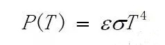
Where P(T) is the radiant energy, σ is the Sterling-Boltzmann constant, and ε is the emissivity. The accuracy of the infrared temperature measurement is closely related to the emissivity of the material to be tested, due to the majority of material emission from the surface of the COB source. The rate is unknown. For accurate temperature measurement, the light source can be placed on a constant temperature heating table. After the light source is heated to a known temperature and is in thermal equilibrium, the surface temperature of the object is measured by an infrared thermal imager, and then the emissivity of the material is adjusted. Make its temperature appear as the correct temperature.
2. The measured temperature of the light-emitting surface is to further study the heat distribution of the COB light source from the experiment. The high-reflectivity mirror aluminum is selected as the substrate. This package structure can greatly improve the light-emitting efficiency on the one hand, and the thermoelectric separation on the other hand. In the form, without the insulation layer of the ordinary aluminum substrate as a barrier, the thermal resistance and junction temperature can be further reduced, and the high luminous flux density output of the COB light source can be realized.
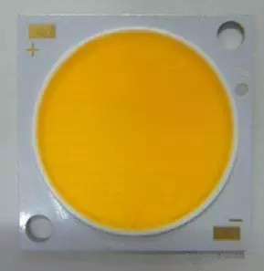
Figure 3: Appearance of the mirrored aluminum COB source to be tested
In addition to the different ratios of fluorescent glues, the other materials are the same, and the colors of the samples to be tested are blue, 2700K and 6500K, respectively. The infrared thermography results for the three samples are shown in Figures 3(a), (b) and (c).
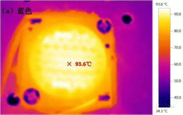

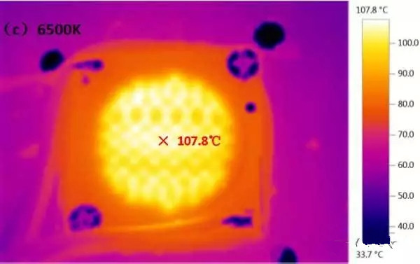
Figure 4: Sample infrared thermography
As can be seen from the figure, the maximum temperature of the luminous surface of the blue sample is 93.6 ° C, the maximum temperature of the luminous surface of 2700 K is 124.5 ° C, and the maximum temperature of the luminous surface of 6500 K is 107.8 ° C.
The difference in temperature can be explained as follows. White light is a blue light-excited phosphor produced by a chip, and the phosphor and silica gel absorb a part of the light and convert it into heat. The photoelectric conversion of the blue sample is measured. The efficiency is 41.6%, the 2700K sample is 32.2%, and the 6500K is 38.5%. The 2700K sample has the lowest photoelectric conversion efficiency. The main reason is that the 2700K sample uses more than 6500K phosphor, and there is more blue light conversion in the blue excitation phosphor process. Heat generation, related parameters refer to Table 2.
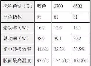
Table 2: Sample photoelectric parameters
3, COB light source heat distribution mechanism From the temperature measurement example in the previous section, the COB light source colloid temperature can reach up to 125 ° C, and most of the current chip can withstand the maximum junction temperature can not exceed 125 ° C, many lighting manufacturers believe that the light When the surface temperature exceeds 125 ° C, the temperature of the chip should be higher, and then the reliability of the COB light source is concerned.
In response to this problem, Eveliina Juntunen, a researcher at the Finnish National Technical Research Center, published an article entitled "Effect of Phosphor Encapsulant on the Thermal Resistance of a" in the July 2013 issue of the IEEE magazine "Components, Packaging and Manufacturing Technology". High-Power COB LED Module" professional article, this article has made in-depth research on the temperature distribution and internal mechanism of COB light source.

Figure 5 is based on the experimental data and simulation. It can be seen from the figure that the temperature of the fluorescent glue can reach 186 ° C, but the chip temperature is only 49.5 ° C. The lower temperature of the chip is because the chip is directly mounted on the aluminum substrate, and the heat of the chip can be quickly transferred to the heat sink through the substrate, so the chip temperature of the COB light source is much lower than the maximum junction temperature allowed by the chip.
The temperature of the fluorescent glue is higher than the temperature of the chip because the number and arrangement density of the COB light source is higher than that of the ordinary SMD device. The light energy density of the fluorescent glue is significantly higher than that of the SMD device, and the phosphor and the silica gel absorb a part of the blue light into The heat, coupled with the lower heat capacity and thermal conductivity of the silica gel, causes the temperature of the fluorescent gel to rise sharply. Therefore, the temperature of the fluorescent rubber when the COB light source is operated will be much higher than the temperature of the chip.
Summary 1. The COB light source is packaged directly on the substrate. The thermal resistance is smaller than that of the SMD device, which is beneficial to the heat dissipation of the chip. In actual operation, the junction temperature of the chip is much lower than the maximum junction temperature allowed by the chip. Due to the multi-chip arrangement of the light source, high lumen density output can be achieved on a small illuminated surface.
2. When the light source is working, the phosphor and silica gel will absorb a part of the light and convert it into heat. The high luminous flux density output will cause the heat of the light-emitting surface to be concentrated, resulting in a higher temperature of the light-emitting surface. If a thermocouple is used to directly measure the temperature of the light-emitting surface, the probe of the thermocouple will also absorb light and convert it into heat, making the temperature measurement higher.
3. Therefore, in order to effectively study the heat distribution on the surface of the COB light source, it is recommended to use an infrared thermal imager for non-contact measurement. Since the temperature of the light-emitting surface of the COB light source is higher than that of the ordinary SMD device, the SMD device is more demanding in the packaging process and material selection, especially for the temperature resistance of the phosphor and the silica gel.
Brushed Dc Motor,Dc Brushed Motor,Brushed Rc Motors,High Torque Brushed Dc Motor
Changzhou Sherry International Trading Co., Ltd. , https://www.sherry-motor.com