CES Electronics Show: Summary and Outlook of the Intelligent Hardware Industry
0 Preface
This article refers to the address: http://
The rapid development of science and technology has greatly improved people's quality of life. As a representative product of high-quality life, smart home has attracted more and more attention. Smart home is a comfortable, safe, convenient and environmentally friendly living environment that combines architecture, communication, network, computer, automatic control and other technologies with the home environment as the platform. It is a comfortable, safe, convenient and environmentally friendly living environment that integrates functionality, service and management. One of the typical applications of high technology in life.
This paper designs and develops a smart home system based on the Cortex-M3 architecture STM32 series chip. The system is based on smart home controllers, including smart sockets, multi-function panels, infrared forwarding, electric curtains, window control modules, light intensity and temperature, hygrometer and other smart home products. It can also be used with infrared detectors and smoke. Security products such as sensor detectors, access controllers, and network cameras form a security system for smart homes. The smart home controller can communicate with the home information interconnection center through Ethernet or Wifi; each intelligent product communicates with the controller through the RS485 bus. The control methods for the system include: upper computer control, touch screen control, or mobile phone, iPAD and other mobile internet products for control. Figure 1 shows the system schematic.
1 The overall design of the smart home control system
1.1 Smart Home Controller
The smart home controller is the core processing module of the smart home system and the key to the entire smart home system. The smart home controller in this design is based on the STM32 chip design and is divided into the following modules according to the functions of the controller: analog acquisition input module, digital output module, RS-485 communication module, ADC conversion module, Ethernet interface. Module, JTAG module, power module, wireless communication module, input and output LED display module. Its hardware structure block diagram is shown in Figure 2.
1.2 Smart Home Products
1.2.1 Smart Socket
The smart socket is based on the STM32 series chip, which contains the ADE7753 power chip, LCD screen, relay, etc. It can measure the power parameters of the corresponding household appliances, and can set when to start the power supply of the household appliances, and can reasonably distribute the power load in the home. To realize the smart grid function, it can communicate with the controller through the 485 bus, or it can work independently.
1.2. 2 multi-function panel
The multi-function panel is based on the STM32 series chip and contains 4 relay outputs. It can control 4 loads (lights, exhaust fans, etc.) at the same time. It can communicate with the controller through the 485 bus, or it can work independently.
1. 2.3 infrared multi-function transponder
The infrared transponder is based on the STM32 series chip. The infrared signal of the remote control of the TV, air conditioner and other electrical appliances can be learned, stored, received and forwarded, and can communicate with the controller through the 485 bus, or can work independently.
1.2. 4 touch screen
The color touch screen used in this design is a high-performance embedded integrated touch screen with embedded low-power CPU as the core (main frequency 400MHz). The product design uses a 7-inch high-brightness TFT liquid crystal display (resolution 800 × 480), four-wire resistive touch screen, high-grade plastic structure, industrial-grade low power consumption, CPU400MHz, 64M memory, 64M flash memory, 1*RS232 (isolated Interface), 1*RS485 (isolated interface), 1*USB interface (one master and one slave), 24VDC power input, power consumption less than 7W. Embedded real-time multitasking operating system configuration software is also pre-installed. It can communicate with the smart home controller through 485, which can realize remote control, remote communication, remote adjustment and scene mode setting.
2 Hardware platform design of smart home system
The main hardware components involved in the smart home controller include STM32F103VET series chip, 8-way Darlington driver ULN2803, 8-way bidirectional optocoupler isolation TLP280-4, 2-way high-speed optocoupler isolation 6N137, 5-way RS485 SN65LBC184, Ethernet ENC28J60, FLASH memory SST25VF016B.
2. 1 STM32F103VET series chip
The STM32F103VET family of chips uses the high-performance ARMCortex-M3 32-bit RISC core operating at 72MHz with built-in high-speed memory (up to 512k bytes of flash and 64K bytes of SRAM) with 512k bytes of flash microcontrollers. Includes three 12-bit ADCs, four general-purpose 16-bit timers, and two PWM timers. It also includes standard and advanced communication interfaces: up to two I2C interfaces, three SPI interfaces, two I2S interfaces, and one SDIO interface, 5 USART interfaces, one USB interface and one CAN interface. USB, CAN, 11 timers, 3 ADCs, 13 communication interfaces. In this design, the pins of the STM32F103VET chip are functionally divided, as shown in Figure 3.
2.2 8-way Darlington connection transistor array ULN2803
8-Channel NPN Darlington Connected Transistor Arrays for low logic level digital circuits such as TTL, CMOS or PMOS/NMOS and high current/voltage requirements for wide range of applications in computer, industrial and consumer applications In lamps, relays, hammers or other similar loads in the product. All devices feature an open collector output and a freewheeling box diode to suppress transitions. The ULN2803 is designed to be compatible with the standard TTL series. It is available in AP=DIP18, AFW=SOL18 package. In this design, ULN2803 is used for the drive circuit of 8-way relay output.
2.3 Bidirectional Optocoupler Isolation TLP280-4 and High Speed ​​Optocoupler Isolation 6N137
The TLP280-4 is an ultra-small and ultra-thin coupler for patch mounting and is commonly used in PCMCIA fax modems and programmable controller circuits. The 6N137 optocoupler is a single-channel high-speed optocoupler with an internal circuit consisting of an 850 nm wavelength AlGaAs LED and an integrated detector. The detector consists of a photodiode, a high-gain linear op amp and a shaw. The special-clamped open-collector triode consists of a clamp. The 6N137 has temperature, current and voltage compensation functions and is widely used in high-speed digital switches, motor control systems and A/D conversion circuits. In this design, TLP280-4 is used to form the 8-channel optocoupler isolation input circuit of the controller. The 6N137 high-speed optocoupler isolation input circuit is used to form the controller.
2.4 RS485 interface communication chip SN65LBC184
In this design, the front-end intelligent device and the detector communicate with each other through the SN65LBC184 in half-duplex mode.
The working principle circuit of SN65LBC184 is shown in Figure 4. The communication direction is controlled by DIR5. When the DIR5 terminal is high level, the controller is in the receiving state, and vice versa, the controller is in the transmitting state.
2.5 Ethernet Module ENC28J60
In this design, each controller can communicate with the home information interconnection processing center through the Ethernet port.
2.6 FLASH memory SST25VF016B
In this design, the FLASH memory SST25VF016B is used to store the IP address of each device.
2. 7 ADE7553 single-phase energy metering chip
The ADE7553 single-phase energy metering chip features high precision and low power consumption. The active energy measurement error is less than 0.1%, with SPI serial communication mode and DI\DT sensor interface, and is powered by 5V Dc Power Supply. There are many registers inside the chip, and you only need to read and write its registers in the design.
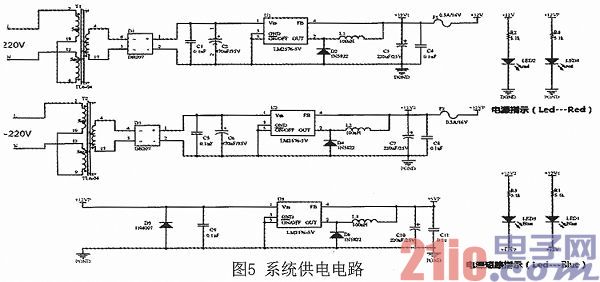
2.8 system power supply circuit
The controller provides dual 12V/0.5A power outputs for use with smart products or modules connected to them. The circuit is shown in Figure 5.
3 Software design of smart home system
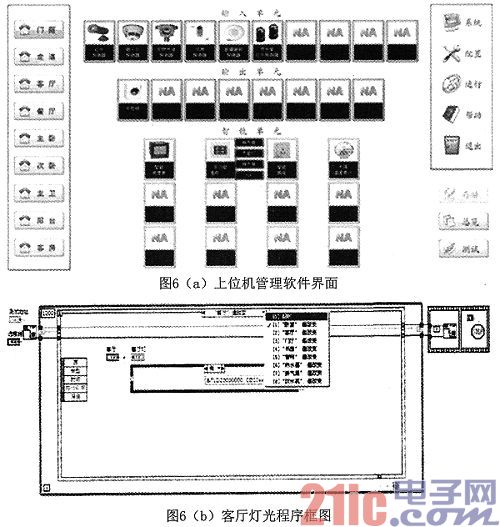
The software design of the entire smart home system mainly includes three parts: smart home PC management software, smart home products (controllers, smart sockets, multi-function panels, etc.), touch screen. Among them, the smart home PC management software is an application software developed based on the LabVIEW development environment, which is a centralized management tool and tool of the system. The software integrates the Ethernet protocol and the underlying control protocol of the smart home controller at the application level, which can realize the control of the home security equipment and electrical equipment, the adjustment of temperature, lighting and other parameters, as well as the scene setting, timing, remote monitoring, etc. Features. Figure 6 shows the host computer management software interface and the living room lighting program block diagram.
The software design of the smart home products is based on the STM32 microcontroller and is written in C language. A driver that contains a controller program and multiple devices. The intelligent module communicates with the controller via the RS485 interface, and the standard serial port driver can be used directly. Much of the work of designing a driver is to "fill in" the functions in the framework based on the hardware structure. The main functions include open(), read(), write(), ioctl(), release(), module_init(), and module_exit().
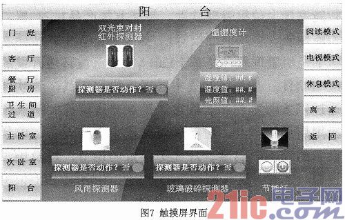
The touch screen communicates with the smart home controller through RS485, and realizes the control of the home equipment and the setting of the situation mode through the pre-installed embedded real-time multi-task operating system configuration software. Figure 7 shows the interface of the touch screen.
4 Conclusion
This paper designs a smart home system based on STM32, including controller, smart meter, smart socket, multi-function panel and other smart home modules. At the same time, with the security products such as infrared detectors, smoke detectors, access controllers, network cameras, etc., a complete smart home system can be built. The system has the advantages of various control modes, flexible module function, simple and easy operation, and is suitable for families, teaching, experimental development and other fields.
- STM32 microcontroller Chinese official website
- STM32 microcontroller official development tools
- STM32 microcontroller reference design
Voltage And Frequency Stabilizer With Three Phase Output
AC Voltage Regulator,Best Voltage Stabilizer,3 Phase Voltage Stabilizer,Three Phase AC Voltage Controller
Jinan Xinyuhua Energy Technology Co.,Ltd , https://www.xyhenergy.com