The light of the traditional car headlights is always the same as the direction of the car body. When the car turns, it can't effectively illuminate the blind spot inside the curve. If there is a person or object inside the curve, and the speed is not properly reduced, it will bring safety hazards. As shown in Figure 1. In comparison, the Automotive Adaptive Headlamp System (AFS) function provides a swiveling adjustment that can be rotated according to the angle of the steering wheel to project an effective beam onto the front surface that the driver needs to see to help reduce Security risks.
This article refers to the address: http://
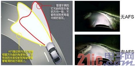
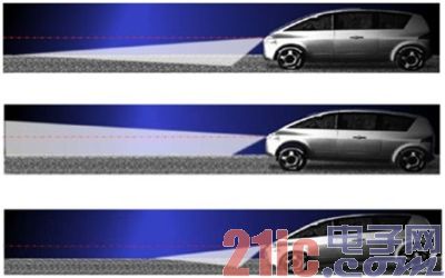
Figure 1: AFS function's rotation adjustment (top) and horizontal adjustment (bottom) lighting effects.
In addition to dynamic rotary adjustment, the AFS function provides dynamic level adjustment. This function adjusts the headlight level according to the signal of the load axis sensor, which can adapt to different loads and different slope environments. As shown in the right side of Figure 1, the above figure shows the effect of the AFS function on the light level under normal conditions. The middle picture shows the effect of the light up under the bumpy condition of the car when starting or going uphill. The figure below is under braking or downhill conditions. The lighting level sinks the lighting effect. It can be seen that AFS can dynamically adjust the light height according to the horizontal tilt of the vehicle body to improve the lighting effect and enhance safety. The structure diagram of AFS working principle is shown in Figure 2 and Figure 3, respectively.
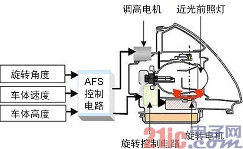
Figure 2: Structure diagram of the working principle of AFS.
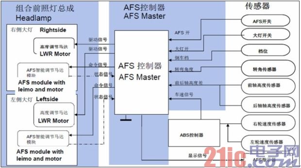
Figure 3: Structure diagram of the working principle of AFS (continued).
Stepper motor driver placement position selection
The rotation and level adjustment of the AFS of the car is realized by using a stepping motor. The motor reacts according to the feedback data of many sensors around the vehicle. Therefore, the designer needs to adopt a suitable stepping motor driving scheme and put it in the suitable s position.
There are two options for the position of the stepper motor driver that controls the AFS function. One method is called direct drive. In this scheme, the stepper motor driver chip is mounted on the same printed circuit board (PCB) as the main microcontroller (MCU). This board is far from the headlamp components and associated stepper motors, and each motor needs to be connected to a corresponding signal.
Another method is mechatronics. In this method, the stepper motor driver IC can be directly mounted in the stepper motor structure, and only the shared ground line is connected to the LIN bus signal. This method is extremely beneficial because the interface between the MCU and the mechatronics module requires only a low electromagnetic compatibility bus. The mechatronics method adopts a modular design, and the headlamp assembly is easy to maintain and maintain, and the benefits are obvious. The structural diagram of the two methods is shown in Figure 4.
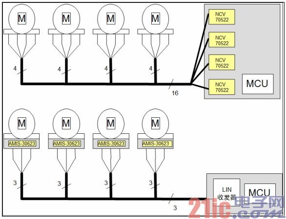
Figure 4: Two different stepper motor driver placement methods.
Av Cable,Rca Cable,Video Cable,Rca Connecter
CHANGZHOU LESEN ELECTRONICS TECHNOLOGY CO.,LTD , https://www.china-lesencable.com