Traffic lights operate based on a well-defined sequence of signals to manage the flow of vehicles and pedestrians at intersections. The system uses three primary signals: red, yellow, and green. When the red light is on, it indicates that vehicles must stop. The yellow light serves as a warning that the signal is about to change, signaling drivers to prepare to stop. The green light means that vehicles are allowed to proceed. This cycle ensures a smooth and safe traffic flow.
The design of a traffic signal control system often involves digital logic circuits. One such design uses the 74LS164 shift register to create a state loop for controlling the traffic lights. This system includes a clock source, a frequency divider, a main controller, and a decoding circuit for driving the signal lights. Additionally, there is a digital display to show the remaining time for each signal, helping both drivers and pedestrians understand when the light will change.
The system operates in different states, with each state corresponding to a specific combination of red, yellow, and green lights. For example, the main road may have a longer green light duration compared to the side road, depending on traffic conditions. A typical setup might include a 48-second green light for the main road and a 24-second green light for the side road, with a 4-second yellow light transition between each phase.
The timing of the signals is controlled by a clock source, usually a 555 timer circuit generating a 1Hz signal. This signal is then divided using 74LS74 flip-flops to produce the necessary time intervals for the traffic lights. The main controller, built around the 74LS164 shift register, manages the sequence of the lights by shifting through its states based on the clock input.
A decoding circuit is used to translate the output of the main controller into control signals for the individual lights. This circuit uses logic gates to determine which lights should be on or off at any given time. The yellow lights are also programmed to flash intermittently during their active period, typically four times per second.
In addition to the signal lights, the system includes a digital display that shows the countdown for each phase. This is achieved using two 74LS190 decrement counters, which count down from a preset value. The display updates in real-time, synchronized with the signal changes. Two 74LS245 multiplexers are used to switch between the main and side road displays, ensuring that the same number is shown in both directions at all times.
The system can be easily modified to adjust the timing of the signals. For instance, the main road could be set to 60 seconds, the side road to 30 seconds, and the yellow light to 5 seconds. This flexibility makes the system adaptable to different traffic conditions and intersection layouts. Overall, the design demonstrates the practical application of digital electronics in real-world systems like traffic control.

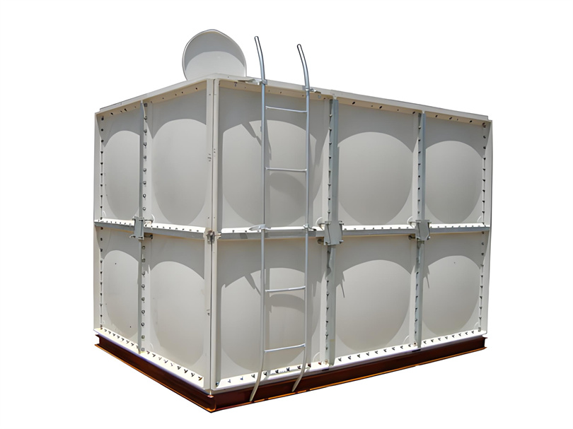
The FRP water tank is assembled from high-quality SMC water tank panels as a whole. Its characteristics are the use of food grade resin, resulting in good water quality, clean and pollution-free. The product has high strength, corrosion resistance, beautiful appearance, long service life, and convenient maintenance and management.

FRP WATER TANK, GRP WATER TANK, FRP PANEL WATER TANK, GRP PANEL WATER TANK, FRP DRINKING WATER TANK
Hebei Dingshengda Composite Material Co., Ltd. , https://www.frpdsd.com