With the rapid development of information technology, wireless remote monitoring technology has been more and more widely used. The wireless monitoring and management system using advanced GPRS technology integrates many advanced technologies such as computer, communication, electromechanical, and automatic control. Realized real-time monitoring and management and flexible deployment of wireless distributed systems, solved the problem that traditional control cannot achieve centralized monitoring due to lack of communication functions, and did not or could not solve the problem of real-time large data processing. Therefore, the design of mobile terminals has also attracted more and more attention. The MC35i module mentioned in this article belongs to the core module of wireless communication. It is a high-tech product that combines voice, data transmission, SMS services and fax functions. This module has powerful functions, and the communication products using this wireless module can well plan the system integration at the client. At present, the application field of the wireless module is relatively extensive, mainly including:
(1) Mobile applications, such as personal digital assistants, smart phones, Internet boards, and notebook computers;
(2) Transportation, such as satellite positioning system, traffic control system, fleet management system, car security system, etc .;
(3) Industrial use, such as wireless public telephone, wireless remote monitoring system, remote instrument and meter communication, etc.
The design described in this paper, combined with single-chip or ARM embedded control, can complete the functions of GPRS data stream transmission and reception of short messages, voice transmission, and data transmission with PC. It has been applied in power line monitoring system based on GPRS data transmission.
1 MC35i module
MC35i is a new generation wireless communication GPRS module launched by Siemens, which can quickly, safely and reliably implement data, voice transmission, short message service (Short Message Service) and fax in the system solution. The working voltage of the module is 3.3 ~ 4.8 V, and it can work in two frequency bands of 900 MHz and 1800 MHz. The power consumption of the frequency band is 2W (900 M) and 1W (1800 M) respectively. The module includes all the functions of the previous version TC35, and at the same time newly added fast GPRS technology, using GPRS time-multiplexed CLASS 8 standard, with always-on function and theoretical transmission rate up to 171.2 kb / s The transmission delay is small, and the longest does not exceed 3s.
The module has an AT command set interface, which supports text and PDU mode short messages, the third group of Type 2 faxes, and non-transparent modes of 2.4k, 4.8k, and 9.6k. In addition, the module also has a phone book function, multi-party calls, roaming detection function, common working modes are power saving mode, IDLE, TALK and other modes. Through the unique 40-pin ZIF connector, the two-way transmission of power connection, command, data, voice signal and control signal is realized. Through the ZIF connector and the 50Ω antenna connector, the SIM card holder and the antenna can be connected separately.
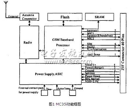
The MC35i module is mainly composed of six parts: GSM baseband processor, GSM radio frequency module, power supply module (ASIC), flash memory, ZIF connector, and antenna interface. As the core of the MC35i, the baseband processor mainly processes voice and data signals in the GSM terminal, and covers all analog and digital functions in cellular radio frequency equipment. Without the need for additional hardware circuits, it can support FR, HR and EFR voice channel coding. The specific structure can refer to FIG. 1.
2 Peripheral application circuit
The proper operation of the MC35i module requires corresponding peripheral circuits to cooperate with it. The MC35i has a total of 40 pins, which are connected to the power circuit, startup and shutdown circuit, data communication circuit, voice communication circuit, SIM card circuit, indicator light circuit, etc. through the ZIF connector.
(1) Start circuit
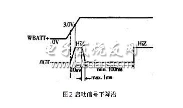
The startup circuit consists of an open-drain transistor and a power-on reset circuit. After the module is powered on for 10 ms (the battery voltage must be greater than 3 V), to make it work properly, a low-level signal with a duration of at least 100 ms must be added to pin 15 (/ IGT), and the falling edge time of the signal is less than 1 ms. After starting, the 15-pin signal should remain high. As shown in Figure 2, for the signal generated by the startup circuit, it can be seen that the delay of 10 m8 and the low level of 100 ms.
According to the above analysis, the reference circuit of the design startup part is as follows:
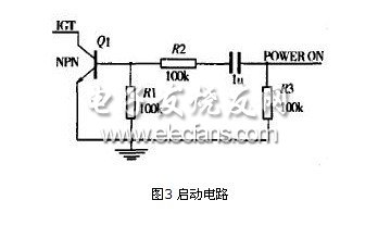
As shown in Figure 3, when the voltage of the Power ON pin changes from low to high, the capacitor C1 is charged left negative and positive. The direction of the current is counterclockwise. At this time, the voltage of resistor R1 is positive and negative (when UR1≥0.7 V), which causes the emitter junction of Q1 to be positively biased, the transistor is in a conducting state, and the IGT pin is at a low level. When the POWER ON pin voltage changes from high to low. The capacitor C1 starts to discharge, and the voltage of the resistor R1 is negative and positive, which reverses the emitter junction of Q1, the transistor is turned off, and the IGT pin is at a high level. Obviously, the IGT pin is at a low level when the POWERON pin voltage changes from low to high, and the GPRS module is turned on. According to the pin requirements, the IGT pin level jumps to a high level after being on the falling edge and staying low for 100 ms ≤ t ≤ 1s. Therefore, there is a requirement for the capacitance of C1, the resistance of R1, R2, and R3. At this time, the capacitance of C1 and the resistance of R1 and R2 need to be adjusted to meet the start-up conditions. For ease of explanation, the circuit diagram of the module startup circuit can be simplified as follows: As shown in Figure 4, the switch is switched from a to b, and the switch is connected to terminal a long enough to reach steady state before t = 0, that is, Uc (0-) = 0 . Since the capacitor voltage cannot jump, the capacitor voltage is still zero at the moment when the switch drops to b. That is, C (0 +) = 0. And when t ≥ 0, the RC circuit is connected to the power supply, so it can be considered as a problem of zero state response.
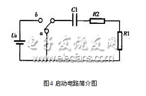
When the switch is turned to b, the capacitor voltage starts to charge from zero, the voltage gradually rises, and finally it should tend to a steady state value. The steady state value is determined as Us based on "capacitance is equivalent to an open circuit". Based on this consideration, it is concluded that:

The voltage on the capacitor rises and the voltage on the resistor gradually decreases. When the voltage on R1 drops to 0.7 V, the transistor will be cut off, so the time when the voltage on R1 drops to 0.7 V must be calculated.
UR1 = i (t) & TImes; R1 (2)
From formula 1, 2, we get: 0.7 = 5 / (200 & TImes; 103) e-1 / 200 & TImes; 200 & TImes; 103. Solved: t = 255 ms. Among them: r = R total × C +; R total = R1 + R2 = 200Ω; r = R total × C + = 200 × 103 × 106 = 200 ms. It can be seen that 100 ms≤255 ms≤1s meets the system requirements.
2.54mm Pitch
2.54mm Pitch
ATKCONN ELECTRONICS CO., LTD , https://www.atkconn.com