The ammeter and voltmeter are the two most basic and most important measuring instruments in the junior high school electrical experiment. The two watches are also the commonly used instruments in the middle school entrance examination. Some students lose points because they do not master their correct use methods, so they teach the students to master the ammeter and The use of voltmeters is very necessary. Let's talk about the few things that must be emphasized in the teaching of ammeters and voltmeters:
1. will look at the table, for example, Figure 1. 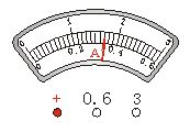
As shown, the dial is marked with the letter "A", which is an ammeter that measures the current intensity. For example Figure 2 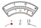
PDM-801A, PDM-801A-C, PDM-801A-F48
As shown, the dial is marked with the letter "V", which is a voltmeter for measuring voltage.
2. The meter should be connected in series to the circuit to be tested. The “+†pole of the ammeter must be extremely close to the “+†of the power supply. The “?†pole of the ammeter must be extremely close to the “?†of the power supply. The voltmeter must be connected in parallel. At both ends of the circuit to be tested, note that the positive and negative poles cannot be reversed. When using an ammeter, its two terminals must not be directly connected to the two poles of the power supply to avoid burning the ammeter due to excessive current.
3. The range current meter and voltmeter of the selected table have three binding posts. See how the wires are connected. For example, if the ammeter is connected to the two terminals “+†and “0.6â€, the measuring range is 0.6 amps. The following set of numbers; for the voltmeter, if connected to the two posts "+" and "15", the range is 15 volts, then the upper set of numbers on the dial should be read. Before the experiment, if you do not know how to connect, you can first estimate the current intensity and voltage value of the circuit. If the estimated current intensity is less than 0.6 ampere, select 0 to 0.6 amp range. If the estimated current intensity is greater than 0.6 ampere, less than 3 amps, then select 0 to 3 ampere range. If it is not possible, use the test method. Fix one terminal and use the other end of the circuit to quickly touch the terminal of the maximum range. According to the test data, select the appropriate range. For the voltmeter, if the estimated voltage is less than 3 volts, the range of 0 to 3 volts is selected. If the estimated value is greater than 3 volts, then the range of 0 to 15 volts should be selected. It cannot be estimated that the test is also performed.
4. After the test circuit is connected to the physical diagram according to the circuit diagram, the test circuit must be connected. Observe the deflection of the pointers of the two tables. If the pointer is not deflected, it means that the circuit is disconnected somewhere, and the positions of the two tables may also be If the pointer is deflected in the opposite direction, the positive and negative terminals are reversed. If the pointer is deflected to the required direction, the range is selected too small. If the range is selected, it is not accurate enough if the pointer is deflected. The direction is too small, indicating that the range is too large. According to the actual situation of the test, the corresponding adjustment can be made, and then the experiment can be carried out.
5. The reading form is very important for the third grade students. Some questions in the middle school test give the position of the two dials and the pointer, so that the corresponding readings can be read out, and the physical quantities such as resistance, electric power, electric power, electric heat, etc. are calculated according to the readings. If one step is wrong, most of the latter questions will be lost. First, figure out what each big grid is, and how much each small grid is. Each large grid represents 0.2 amps (Figure 1). Each small grid scale represents 0.02 amps. At this time, it can be accurate to 0.02 amps, and then look at the pointer position. The position indicated by the pointer is 1 large grid and 8 small grids, then the reading should be 0.36 amps.
In Figure 2, each large cell represents 5 volts, and each small cell is expressed as 0.5 volts. At this time, it can be accurate to 0.5 volts, and then look at the position of the pointer. The position of the pointer is 2 large cells and 4 small cells. , then the reading should be 12 volts.
6. It will distinguish the similarities and differences between the two tables: 1 The positive poles of both tables are close to the positive pole of the power supply. 2 Both tables should pay attention to the measurement range. Different points: 1 The ammeter must be connected in series in the circuit to be tested, and the voltmeter must be connected in parallel at both ends of the circuit to be tested. 2 The ammeter cannot be directly connected to the two poles of the power supply. The voltmeter can be directly connected to the two poles of the power supply.
Pv Ribbon Machine,Solar Pv Ribbon Machine,Ribbon Machine,High Efficiency Pv Ribbon Machine
Jiangsu Lanhui Intelligent Equipment Technology Co., Ltd , https://www.lanhuisolar.com