Megger is commonly known as a shaker. It is a special instrument commonly used to measure electrical equipment, cable insulation resistance and high value resistance. It is a portable instrument that does not measure electrical equipment and line insulation resistance. It masters the use of megohmmeter. Is the basic skills of electricians, this article describes the use of megohm meters.
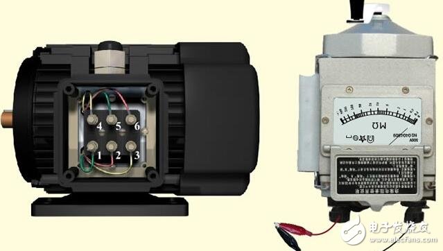
Megohmmeter structureThe megohmmeter is mainly composed of a manual DC generator, a magnetoelectric flow ratio meter, and three terminals (ie, L: line end, E: ground end, G: shield end).
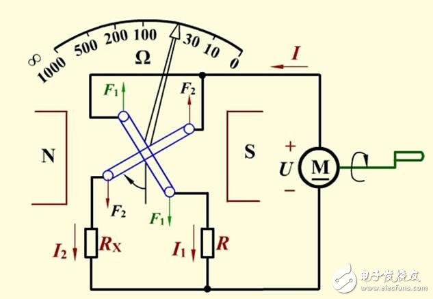
Megohmmeter worksThe movable portion of the flow meter has two coils that are opposite to each other and at an angle to each other, and the magnetic induction in the air gap is uneven. The coil 1 is used to generate a rotational moment and the coil 2 is used to generate a reaction torque. The measured resistance is connected to the L (line) and E (ground) terminals, forming two loops, one is the current loop and the other is the voltage loop. The current loop is returned from the positive terminal of the power supply through the measured resistance Rx, the current limiting resistor RA, and the movable coil 1 to the negative terminal of the power supply. The voltage loop is returned from the positive terminal of the power supply via the current limiting resistor RV and the movable coil 2 to the negative terminal of the power supply. Since the magnetic induction in the air gap is not uniform, the torques T1 and T2 generated by the two coils are related not only to the currents I1, I2 flowing through the coil but also to the deflection angle α of the movable portion.
The current limiting resistors RA and RV are fixed values. When the generator voltage is constant, the current I2 of the voltage loop is constant, and the magnitude of the current loop current I1 is inversely proportional to the magnitude of the measured resistance Rx, so the deflection angle of the pointer of the flow ratio meter α can directly reflect the size of the measured resistance Rx.
The deflection angle of the flow meter pointer is independent of the change of the power supply voltage. The fluctuation of the power supply voltage U is the same as the interference of the rotational torque and the reaction torque, so the accuracy of the flow ratio meter is independent of the voltage.
Diagram of the use of megohmmeter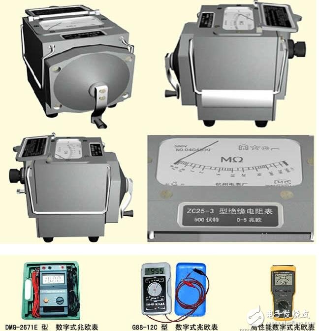
The main components of the megohmmeter are a magnetoelectric flowmeter and a hand-cranked generator. The generator is a megohmmeter power supply, which can be a DC generator or an alternator and a rectifier. The capacity of a DC generator is small, but the voltage is high (100-5000V). The magnetoelectric flowmeter is a megohmmeter measuring mechanism consisting of a fixed permanent magnet and two coils that can rotate in a magnetic field.
First, preparation before use
Step 1: Check if the megohmmeter works properly and place the megohmmeter horizontally.
Step 2: Empty the megger handle, the pointer should point to infinity (leftmost).
Step 3: Short-circuit the output lines of the L and E wiring posts, and then slowly shake the handle. The pointer should quickly point to zero (far right).
1. Be careful not to let L and E short-circuit for too long when shaking the handle, otherwise the megger will be damaged.
2. Check the electrical equipment and circuits under test to see if all power has been cut off. It is absolutely not allowed to measure with a megohmmeter when the equipment and lines are energized.
3. Before the measurement, the equipment and the line should be discharged first, so as to avoid the discharge of the capacitor of the equipment or the line, which endangers the personal safety and damages the megohmmeter. This can also reduce the measurement error, and at the same time, wipe the tested points clean.
4. The megohmmeter must be placed horizontally in a stable and stable place to avoid measurement errors caused by jitter and tilt when shaking.
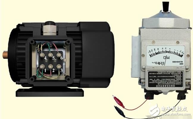
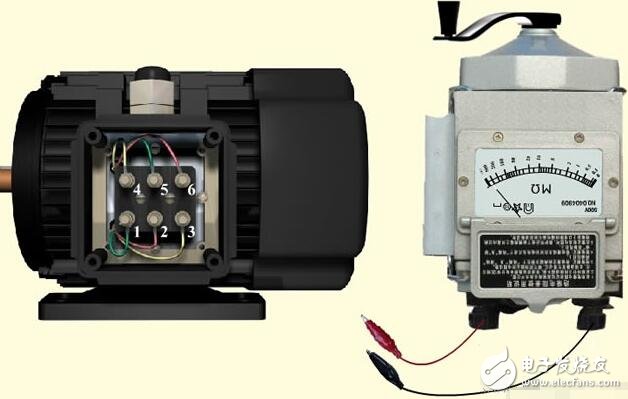
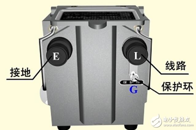
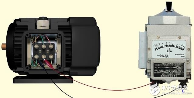
5, the wiring must be correct, the megohmmeter has three wiring posts, "E" (ground), "L" (line) and "G" (protective ring or shield terminal). When measuring the insulation resistance of the electrical equipment to the ground, the "L" is connected to the part to be tested of the equipment by a single wire, and the "E" is connected to the equipment casing by a single wire.
6. If the insulation resistance between the two windings in the electrical equipment is measured, connect "L" and "E" to the terminals of the two windings.
7. When measuring the insulation resistance of the cable, in order to eliminate the error caused by surface leakage, the "L" terminal, the "E" is connected to the outer casing, and the insulation layer between the "G" terminal and the outer casing.
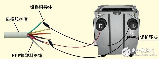
8. The connecting line of "L", "E", "G" and the measured object must be a single wire, which is well insulated and must not be twisted. The surface must not be in contact with the object to be measured.
9. The rotation speed of the rocking handle should be uniform, generally specified as 120 rpm, which is allowed to change by ±20%, and should not exceed ±25%. Usually shake for a minute, wait until the pointer stabilizes and read. If there is a capacitor in the circuit under test, first keep shaking for a period of time, let the megohmmeter charge the capacitor, and then read the pointer after the indicator is stable. After the measurement, remove the wiring and stop shaking. If the pointer is found to be zero during the measurement, stop shaking the handle immediately.
10. After the measurement is completed, the equipment with energy storage components should be fully discharged, otherwise it will easily cause electric shock.
11. It is forbidden to measure the insulation resistance on equipment with high voltage conductors at or near lightning. It can only be measured if the device is not powered and cannot be charged by other power sources.
12. Before the megohmmeter has stopped rotating, do not touch the measuring part of the equipment or the megohmmeter wiring pile by hand. It is also not possible to directly touch the bare part of the lead when disconnecting the wire.
13. The megohmmeter should be checked regularly. The calibration method is to directly measure the standard resistance with a certain value and check whether the measurement error is within the allowable range.
Megohmmeter reading method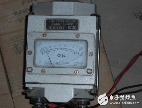
The ohmmeter starts from the left, first ohmic, then 100 ohms, then kΩ (kilo ohms).
With the advancement of technology, LED technology has been applied to projectors. There are many good domestic LED projector manufacturers in the market. For example, Shenzhen Resources has perfectly combined this technology with DLP technology to make it portable and compact. Because of its low power consumption and heat generation, it is more widely used in life and in personal business. The same goes for LED hotel projectors.
portable led projector,led home theater projector,led holiday projector,led room light projector,led 4k projectors
Shenzhen Happybate Trading Co.,LTD , https://www.szhappybateprojector.com