Motors are used in a wide range of industrial, automotive and commercial applications. The motor is controlled by a drive that controls its torque, speed and position by changing the input power. High-performance motor drives increase efficiency for faster, more precise control. The advanced motor control system combines control algorithms, industrial networks and user interfaces, so more processing power is required to perform all tasks in real time. Modern motor control systems are typically implemented using a multi-chip architecture: a digital signal processor (DSP) that performs motor control algorithms, an FPGA that implements high-speed I/O and network protocols, and a microprocessor that handles execution control.
With the advent of system-on-a-chip (SoC), such as the Xilinx® Zynq All Programmable SoC, which combines the flexibility of the CPU with the processing power of the FPGA, designers are finally able to incorporate motor control functions and other processing tasks into a single device. Control algorithms, networks, and other processing-intensive tasks are offloaded to programmable logic, while management control, system monitoring and diagnostics, user interfaces, and debugging are handled by the processing unit. Programmable logic can contain multiple control cores operating in parallel to implement a multi-axis machine or multiple control systems. Since a complete controller is implemented on a single chip, the hardware design can be simpler, more reliable, and less expensive.
In recent years, model-based design has evolved into a complete design process – from model creation to implementation 2 – driven by software modeling and simulation tools such as MathWorks Simulink. Model-based design changes the way engineers and scientists work, moving design tasks from the lab and the field to the desktop. Now, the entire system, including the plant and controller, can be modeled, and engineers can adjust the behavior of the controller before deploying it to the site. This reduces the risk of damage, accelerates system integration, and reduces reliance on equipment supply. Once the control model is complete, the Simulink environment automatically converts it to C and HDL code that is run by the control system, saving time and avoiding manual programming errors. Linking the system model to the rapid prototyping environment further reduces risk because the latter allows the observation controller to operate under real-world conditions.
A complete development environment for higher motor control performance with Xilinx ZynqSoC for controllers, MathWorks Simulink for model-based design and automatic code generation, and Analog Devices' intelligent driver kit for rapid development of drive system prototypes.
Xilinx FPGA and SoC Motor Control Solutions
Advanced motor control systems must fully perform control, communication, and user interface tasks, each with different processing bandwidth requirements and real-time constraints. In order to implement such a control system, the chosen hardware platform must be robust and scalable to create conditions for future system improvements and expansions. The Zynq All Programmable SoC combines a high-performance processing system with programmable logic to meet these requirements (see Figure 1). This combination provides excellent parallel processing, real-time performance, fast calculations, and flexible connectivity. The SoC integrates two Xilinx analog-to-digital converters (XADCs) for monitoring systems or external analog sensors.
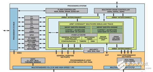
Figure 1. Xilinx Zynq SoC Functional Block Diagram
Zynq includes a dual-core ARM Cortex-A9 processor, a NEON coprocessor, and multiple floating-point expansion units for accelerated software execution. The processing system handles tasks such as management control, motion control, system management, user interface, and remote maintenance. These functions are ideal for implementation in software. In order to take advantage of the system's capabilities, you can use embedded Linux or real-time operating systems. You can use a self-sufficient processor without having to configure programmable logic. In this way, the software developer can write the code and the hardware engineer can design the FPGA structure at the same time.
In terms of programmable logic, the device has up to 444,000 logic cells and 2,200 DSP slices, providing tremendous processing bandwidth. The FPGA architecture is scalable, allowing users to choose from a wide range of devices ranging from 28,000 logic cells to high-end devices supporting the most challenging signal processing applications. Five AMBA-4 AXI high-speed interconnects tightly couple programmable logic to the processing system, providing an effective bandwidth equivalent to more than 3000 pins. Programmable logic is suitable for performing time-critical processing-intensive tasks such as real-time industrial Ethernet protocols, and it supports multiple control cores working in parallel to implement multi-axis machines or multiple control systems.
The Xilinx All Programmable SoC-based solutions and platforms address the critical timing and performance requirements of today's complex control algorithms such as Field Oriented Control (FOC) and complex modulation schemes such as the Regenerative Pulse Frequency Modulators designed by Xilinx and Qdesys.
Model-based design with MathWorks Simulink
Simulink is a block diagram environment that supports multi-domain simulation and model-based design, and is ideal for simulating systems that include control algorithms and plant models. For precise positioning and other purposes, the motor control algorithm adjusts speed, torque and other parameters. The simulation evaluation control algorithm can effectively determine whether the motor control design is appropriate, and judge the appropriateness before performing expensive hardware testing, thereby reducing the time and cost of algorithm development. Figure 2 shows the effective workflow for designing a motor control algorithm:
Build accurate controller and plant models, often based on a library of motors, drive electronics, sensors and loads
Simulate system behavior to verify that the controller's performance is as expected
Generate C code and HDL for real-time testing and implementation
Prototype hardware test control algorithm
After simulation and testing on the prototype hardware, if the control system proves satisfactory, deploy the controller to the final production system
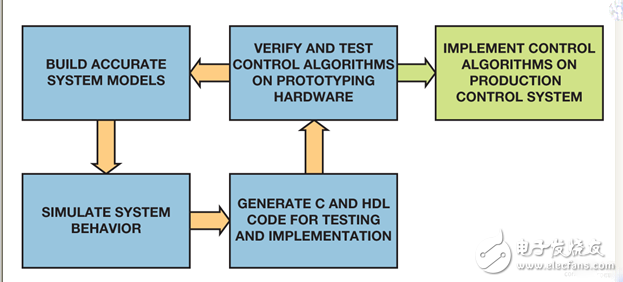
Figure 2. Workflow for motor control algorithm design
MathWorks products include Control System ToolboxTM, SimPowerSystemsTM and SimscapeTM, providing industry-standard algorithms and applications for systematic analysis, design and tuning of linear control systems, as well as component libraries and analysis tools for mechanical and electrical applications. Modeling and simulation of various systems in hydraulics and other physical fields. These tools allow you to create high-fidelity plant and controller models that validate the behavior and performance of your control system, and then hand over the actual implementation. This simulation environment is an ideal place to verify extreme functional conditions and operating conditions, ensuring that the controller is ready for these conditions and that its actual operation will be safe for both the equipment and the staff.
Once the control system has been fully validated in the simulation environment, it can be converted to C code and HDL using embedded transcoders and HDL transcoding tools, deployed to prototype hardware for testing, and then deployed to the final production system. . At this time, specify hardware and software implementation requirements such as fixed point and timing behavior. Automated code generation helps reduce the time required from concept to actual system implementation, eliminates programming errors, and ensures that actual results match the model. Figure 3 shows the actual steps required to model the motor controller in Simulink and transfer it to the final production system.
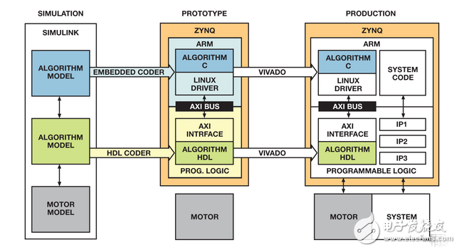
Figure 3. Process from simulation to production
The first step is to model and simulate controllers and plants in Simulink. At this stage, the controller algorithm is divided into modules implemented in software and modules implemented in programmable logic. After the partitioning and simulation are completed, the controller model is converted to C code and HDL using an embedded transcoder and an HDL transcoder. The Zynq-based prototype system verifies the performance of the control algorithm and helps to further tune the controller model and then move to the production phase. In the production phase, the automatically generated C code and HDL are integrated into a complex production system framework. This workflow ensures that the control algorithm is fully validated and tested before it reaches the production stage, making system robustness highly credible.
Description of Electrical Cord Sleeves For Insulation Cable Protection
High flame retardant braided sleeving is braided by UL 94 VO grade raw material PET mono filaments. It has excellent expandability, abrasive resistance and high flame retardant. Its flame rating can be up to VW-1.
Application electronics, automobile, high-speed rail,aviation, marine and switch cabinet wire harnessing applications where cost efficiency and durability are critical. The unique braided construction and wide expandability allows quick and easy installation over large connectors and long runs.
Ease of installation and nearly complete coverage makes fray resistance braided sleeve an ideal solution for many industrial and engineering applications.
The Cable Wire Sleeve has smooth surface, bright color and various patterns. It is an ideal product for line management and bundle application of electronics, automobiles, airplanes, ships, industry and home. For example, DVI wire mesh sets, HDMI wire net sets, motor vehicle engine line dressing, home theater wire management, computer chassis wire layout, office line management, car wiring harness, water tube protection.
Electrical Cord Sleeves
Flame Retardant Braided Sleeve,Electrical Cable Sleeving ,Wear Proof Cable Sleeve,Heat Resistant Wire Sleeve
Shenzhen Huiyunhai Tech.Co.,Ltd , https://www.hyhbraidedsleeve.com