Describes ways to help the automotive lighting industry achieve optimal thermal management. We discussed the selection and measurement of LED thermal characteristics and the selection of the most appropriate LED for a particular application. Since overheating can disrupt the stability of the LED system, we also discuss the thermal simulation of complex lighting systems such as headlights and taillights, and the use of synchronous computational fluid dynamics to design higher quality products faster and more Develop automotive lighting systems in an efficient and cost-effective way.
According to McKinsey & Company's insights into the global lighting market, the automotive lighting market is currently approximately $18 billion (13 billion euros), accounting for approximately 20% of the entire lighting market and is expected to increase to $25 billion by 2020. (18 billion euros). With the development of LEDs, LEDs in automotive applications are expected to grow significantly over the next 10 years. According to an article published in November 2012 by LEDs Magazine, LEDs will be used in all lighting systems of Daimler's upcoming S-series Mercedes. From 2010 to 2020, the price of LEDs will be reduced to one-tenth of the current price, so LEDs will be more competitive than traditional light sources. Unlike traditional automotive lighting sources, LEDs are more sensitive to temperature, not just need A good understanding of the structure and characteristics of the LEDs used in the design requires an understanding of the entire thermal management system from the heat sink to the cooling fluid. With these skills, lighting designers can optimize their designs to ensure long-lasting LEDs with minimal emission wavelength shift or minimal light output loss. They can also use LEDs as a light source more effectively and drive the full popularity of LEDs in the automotive industry.
The challenge of using LEDs in automotive lighting
As light source designs shift from incandescent to LED, traditional thermal management concepts are outdated and new ways of thinking are needed. About 83% of the energy of most incandescent lamps forms heat radiation, and about 12% forms heat loss, which does not face the problem of heat dissipation from the light source. LEDs mostly transfer heat loss through conduction (about 60-85%) and are very sensitive to thermal management. The 100 watt incandescent lamp has an electro-optic conversion efficiency of only about 5%, and the conversion efficiency of the LED can reach about 15-40%, and is still increasing.
The main thermal challenge for LEDs is to maintain high chroma stability and life expectancy. LEDs in the automotive industry require lifetime tolerance. LEDs are not only more efficient, but their higher visibility is also valuable and therefore safer. The European Economic Commission (ECE) requires that all new cars be equipped with daytime running lights (DRL) from 2011 onwards. Because external lights such as headlights and taillights are almost completely sealed systems (except for small airflow inlets, outlets, and small openings for ordinary incandescent lamps), it is unrealistic to replace LEDs with a flaw. When multiple LEDs of the headlights or taillights fail, they can only be solved by replacing the entire lamp. Therefore, not only LEDs, but the entire luminaire design must have high reliability and quality, because replacing the entire headlight is expensive; if it is still under warranty, then the original equipment manufacturer (OEM) and supplier of the system will It costs a lot. Original supplier data sheets do not always provide the data needed to derive accurate and reliable simulation results from fluid or structural analysis; manufacturers do not often provide assurance or instructions for measurement data errors. Therefore, you will need to test and measure the characteristics of your vehicle before installing it to ensure the reliability of parts and materials.
Thermal characteristics
The thermal resistance (Rth) of an LED affects product life, efficiency, and operation of multiple domains as well as electrical, thermal, and optical performance (Figure 1). Like all other semiconductor device kits, the LED kit provides excellent characterization through thermal resistance for stable operation. The thermal resistance (Rth) value tells us how many degrees of temperature increase can be caused by the application of a unit heat source to the device.
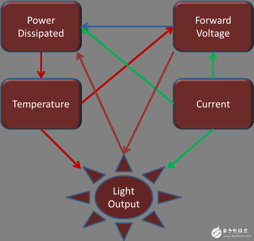
Figure 1: Thermal issues affect every aspect of the LED package.
The most basic method is to measure the temperature-dependent voltage of the component. The LED turns on or off from a stable state, and after a while, it reaches another stable state (hot/cold, and vice versa). Transient measurements are continuously performed during this process, providing a thermal transient response curve at very small measured currents. With the help of the measured temperature difference and power difference (for the switching components) (Figure 2), the structure function can be derived (Figure 3).
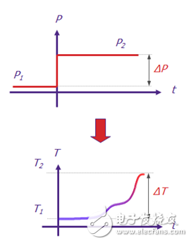
Figure 2: Mentor Graphics' T3Ster Thermal Transient Tester records the transient response of an LED after a short period of 1 microsecond (1 x 10⁻⁶ seconds) with a temperature resolution of 0.01 °C.
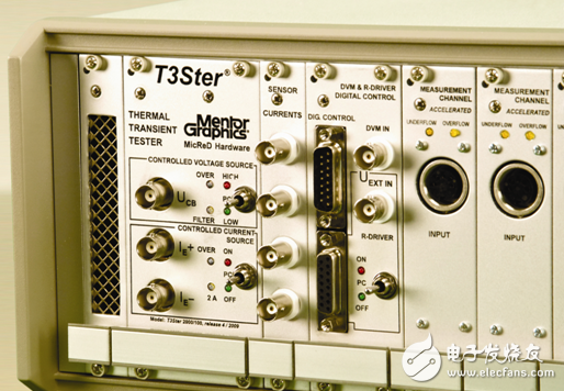
Figure 3: Through the transient response, we can automatically determine the structure function of the LED kit samples. This R/C mode can be used directly in thermal simulation software.
In November 2010, the Joint Electron Devices Engineering Council (JEDEC) released the standard JESD51-14 [1] using the dual thermal interface method for the measurement of the thermal resistance of the shell (RthJC) [1]. The standard requires two measurements: that is, separately measured without additional layers and with additional layers that reflect the thermal resistance of a component. This method is suitable for power semiconductor components with exposed cooling surfaces and one-dimensional heat flow paths. This situation is also effective for power LEDs.
The structure function shown in Figure 3 allows us to determine the thermal resistance crust (RthJC), which is very important for accurate thermal simulation. The structure function not only helps determine the thermal resistance, but also compares the different LEDs, solder/binder quality, crucible and crucible position, cooling efficiency and temperature dependence of different PCB/MCPCB types. Everything between the grain and the surrounding environment can be seen in the structure function, and the changes due to enthalpy and aging can also be seen by comparison with normal or ideal assembly.
Battery Lithium Ion,Lithium Ion Battery 24V 100Ah,48V100Ah Lithium Ion Battery,Lithium Iron Phosphate Battery
Jiangsu Stark New Energy Co.,Ltd , https://www.stark-newenergy.com