Abstract: Class D amplifiers have higher efficiency and better thermal performance than class AB amplifiers. Nevertheless, the use of Class D amplifiers still requires careful consideration of their heat dissipation. This application note analyzes the thermal performance of Class D amplifiers and illustrates the principles that a good design should follow through a few common examples.
Continuous sine wave and music When evaluating the performance of Class D amplifiers in the laboratory, the continuous sine wave is often used as the signal source. Although it is more convenient to use a sine wave for the measurement, such a measurement result is the thermal load of the amplifier in the worst case. If a continuous sine wave near the maximum output power is used to drive a Class D amplifier, the amplifier will often enter a thermal shutdown state.
Common audio sources, including music and speech, often have a much lower RMS value than the peak output power. Normally, the ratio of peak voice to RMS power (crest factor) is 12dB, while the crest factor of music is 18dB to 20dB. Figure 1 shows the waveform diagram of the audio signal and sine wave in the time domain, and shows the results of measuring the RMS value of both using an oscilloscope. Although the peak value of the audio signal is slightly higher than the sine wave, its RMS value is only about half of the sine wave. Similarly, there may be sudden changes in the audio signal, but as the measurement results show, the average value is still much lower than the sine wave. Although the audio signal may have a peak value similar to a sine wave, the thermal effect exhibited in a class D amplifier is much lower than that of a sine wave. Therefore, when measuring the thermal performance of the system, it is best to use the actual audio signal instead of a sine wave as the signal source. If only sine waves can be used, the resulting thermal performance is worse than the actual system.
Figure 1. The RMS value of the sine wave is higher than the RMS value of the audio signal, which means that the class D amplifier generates more heat when tested with a sine wave.
PCB heat dissipation considerations In the industry standard TQFN package, the exposed pad is the main way of IC heat dissipation. For packages with exposed pads on the bottom, the PCB and its copper layer are the main heat dissipation channels for Class D amplifiers. As shown in Figure 2, when mounting a Class D amplifier to a common PCB, it is best to follow the following principle: solder the exposed pad to a large area copper block. As much as possible, place more copper between the copper block and the adjacent D-type amplifier pins with equal potential and other components. In the case of this article, the copper layer is connected to the upper right and lower right of the heat dissipation pad (Figure 2). The copper traces should be as wide as possible, as this will affect the overall heat dissipation performance of the system.
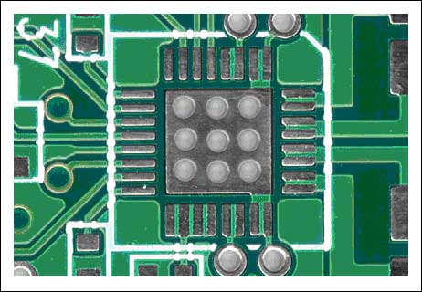
Figure 2. When the Class D amplifier is packaged in a TQFN or TQFP, the exposed pad is its main heat dissipation channel.
The copper pad connected to the exposed pad should be connected to other copper pads on the back of the PCB with multiple vias. The copper-clad block should have as large an area as possible while meeting the requirements of the system signal wiring.
Try to widen all connections with the device, which will help improve the system's heat dissipation performance. Although the pins of the IC are not the main heat dissipation channels, there will still be a small amount of heat in practical applications. In the PCB shown in Figure 3, a wide wire is used to connect the output of the Class D amplifier to the two inductors on the right side of the figure. In this case, the copper winding of the inductor can also provide additional heat dissipation channels for the D amplifier. Although the overall thermal performance is improved by less than 10%, such an improvement will bring two very different results to the system-even if the system has better heat dissipation or more severe heat generation.
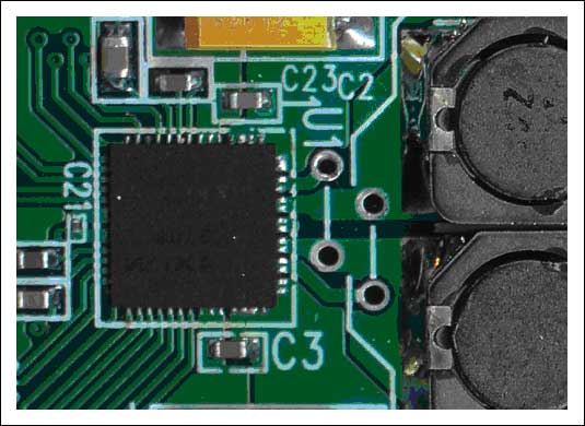
Figure 3. The wide trace to the right of the Class D amplifier helps conduct heat
Auxiliary heat dissipation When the Class D amplifier operates at a higher ambient temperature, adding an external heat sink can improve the thermal performance of the PCB. The thermal resistance of the heat sink must be as small as possible to maximize the heat dissipation performance. After using the exposed pad on the bottom, the bottom of the PCB is often the heat dissipation channel with the lowest thermal resistance. The top of the IC is not the main heat dissipation channel of the device, so it is not cost-effective to install a heat sink here. Figure 4 shows a PCB surface-mount heat sink (218 series, provided by Wakefield Engineering). The heat sink is soldered on the PCB, which is an ideal choice considering size, cost, ease of assembly and heat dissipation performance.

Figure 4. When the Class D amplifier is operated at a higher ambient temperature, the SMT heat sink as shown in the figure may be required (picture from Wakefield Engineering).
Thermal calculation The die temperature of a Class D amplifier can be estimated by some basic calculations. In this example, the temperature is calculated based on the following conditions: TAM = + 40 ° C POUT = 16W Efficiency (η) = 87% ΘJA = 21 ° C / W First, calculate the power consumption of the Class D amplifier:
Then, the die temperature TC is calculated by power consumption, the formula is as follows:

Based on these data, it can be inferred that the device has a relatively ideal performance during operation. Because the system rarely works at an ideal ambient temperature of + 25 ° C, it should be reasonably estimated based on the actual ambient temperature of the system.
The on-resistance of the load impedance class D amplifier MOSFET output stage will affect its efficiency and peak current capability. Reducing the peak current of the load can reduce the I²R losses of the MOSFET, thereby improving efficiency. To reduce the peak current, the speaker with the highest impedance should be selected under the conditions of ensuring the output power, the voltage swing of the class D amplifier and the power supply voltage, as shown in Figure 5. In this example, assume that the output current of the Class D amplifier is 2A, and the power supply voltage range is 5V to 24V. When the power supply voltage is greater than or equal to 8V, the load current of 4Ω will reach 2A, and the corresponding maximum continuous output power is 8W. If the output power of 8W can meet the requirements, you can consider using a 12Ω speaker and 15V supply voltage. At this time, the peak current is limited to 1.25A, and the corresponding maximum continuous output power is 9.4W. In addition, the operating efficiency of the 12Ω load is 10% to 15% higher than that of the 4Ω load, reducing power consumption. The actual efficiency improvement varies with different Class D amplifiers. Although the impedance of most speakers is 4Ω or 8Ω, other impedance speakers can also be used to achieve more efficient heat dissipation.
Figure 5. Choose the best impedance and supply voltage to maximize the output power.
Also need to pay attention to the change of load impedance within the audio bandwidth. The loudspeaker is a complex electromechanical system with multiple resonance elements. In other words, 8Ω speakers only exhibit 8Ω impedance in a very narrow frequency band. In most audio bandwidths, the impedance will be greater than its nominal value, as shown in Figure 6. In most audio bandwidths, the impedance of this speaker will be much greater than its nominal value of 8Ω. However, the presence of high-frequency speakers and crossover networks will reduce the impedance value. Therefore, the total impedance of the system must be considered to ensure sufficient current driving capability and heat dissipation performance.
Figure 6. The impedance of an 8Ω, 13cm-diameter speaker changes dramatically with frequency.
Conclusion The efficiency of Class D amplifiers is greatly improved compared to Class AB amplifiers. Although this efficiency advantage reduces the design requirements for heat dissipation during system design, the system heat dissipation cannot be completely ignored. However, if you can follow good design principles and set reasonable design goals, using Class D amplifiers can make audio system design simpler.
Common audio sources, including music and speech, often have a much lower RMS value than the peak output power. Normally, the ratio of peak voice to RMS power (crest factor) is 12dB, while the crest factor of music is 18dB to 20dB. Figure 1 shows the waveform diagram of the audio signal and sine wave in the time domain, and shows the results of measuring the RMS value of both using an oscilloscope. Although the peak value of the audio signal is slightly higher than the sine wave, its RMS value is only about half of the sine wave. Similarly, there may be sudden changes in the audio signal, but as the measurement results show, the average value is still much lower than the sine wave. Although the audio signal may have a peak value similar to a sine wave, the thermal effect exhibited in a class D amplifier is much lower than that of a sine wave. Therefore, when measuring the thermal performance of the system, it is best to use the actual audio signal instead of a sine wave as the signal source. If only sine waves can be used, the resulting thermal performance is worse than the actual system.
Figure 1. The RMS value of the sine wave is higher than the RMS value of the audio signal, which means that the class D amplifier generates more heat when tested with a sine wave.
PCB heat dissipation considerations In the industry standard TQFN package, the exposed pad is the main way of IC heat dissipation. For packages with exposed pads on the bottom, the PCB and its copper layer are the main heat dissipation channels for Class D amplifiers. As shown in Figure 2, when mounting a Class D amplifier to a common PCB, it is best to follow the following principle: solder the exposed pad to a large area copper block. As much as possible, place more copper between the copper block and the adjacent D-type amplifier pins with equal potential and other components. In the case of this article, the copper layer is connected to the upper right and lower right of the heat dissipation pad (Figure 2). The copper traces should be as wide as possible, as this will affect the overall heat dissipation performance of the system.
Figure 2. When the Class D amplifier is packaged in a TQFN or TQFP, the exposed pad is its main heat dissipation channel.
The copper pad connected to the exposed pad should be connected to other copper pads on the back of the PCB with multiple vias. The copper-clad block should have as large an area as possible while meeting the requirements of the system signal wiring.
Try to widen all connections with the device, which will help improve the system's heat dissipation performance. Although the pins of the IC are not the main heat dissipation channels, there will still be a small amount of heat in practical applications. In the PCB shown in Figure 3, a wide wire is used to connect the output of the Class D amplifier to the two inductors on the right side of the figure. In this case, the copper winding of the inductor can also provide additional heat dissipation channels for the D amplifier. Although the overall thermal performance is improved by less than 10%, such an improvement will bring two very different results to the system-even if the system has better heat dissipation or more severe heat generation.
Figure 3. The wide trace to the right of the Class D amplifier helps conduct heat
Auxiliary heat dissipation When the Class D amplifier operates at a higher ambient temperature, adding an external heat sink can improve the thermal performance of the PCB. The thermal resistance of the heat sink must be as small as possible to maximize the heat dissipation performance. After using the exposed pad on the bottom, the bottom of the PCB is often the heat dissipation channel with the lowest thermal resistance. The top of the IC is not the main heat dissipation channel of the device, so it is not cost-effective to install a heat sink here. Figure 4 shows a PCB surface-mount heat sink (218 series, provided by Wakefield Engineering). The heat sink is soldered on the PCB, which is an ideal choice considering size, cost, ease of assembly and heat dissipation performance.
Figure 4. When the Class D amplifier is operated at a higher ambient temperature, the SMT heat sink as shown in the figure may be required (picture from Wakefield Engineering).
Thermal calculation The die temperature of a Class D amplifier can be estimated by some basic calculations. In this example, the temperature is calculated based on the following conditions: TAM = + 40 ° C POUT = 16W Efficiency (η) = 87% ΘJA = 21 ° C / W First, calculate the power consumption of the Class D amplifier:
Then, the die temperature TC is calculated by power consumption, the formula is as follows:
Based on these data, it can be inferred that the device has a relatively ideal performance during operation. Because the system rarely works at an ideal ambient temperature of + 25 ° C, it should be reasonably estimated based on the actual ambient temperature of the system.
The on-resistance of the load impedance class D amplifier MOSFET output stage will affect its efficiency and peak current capability. Reducing the peak current of the load can reduce the I²R losses of the MOSFET, thereby improving efficiency. To reduce the peak current, the speaker with the highest impedance should be selected under the conditions of ensuring the output power, the voltage swing of the class D amplifier and the power supply voltage, as shown in Figure 5. In this example, assume that the output current of the Class D amplifier is 2A, and the power supply voltage range is 5V to 24V. When the power supply voltage is greater than or equal to 8V, the load current of 4Ω will reach 2A, and the corresponding maximum continuous output power is 8W. If the output power of 8W can meet the requirements, you can consider using a 12Ω speaker and 15V supply voltage. At this time, the peak current is limited to 1.25A, and the corresponding maximum continuous output power is 9.4W. In addition, the operating efficiency of the 12Ω load is 10% to 15% higher than that of the 4Ω load, reducing power consumption. The actual efficiency improvement varies with different Class D amplifiers. Although the impedance of most speakers is 4Ω or 8Ω, other impedance speakers can also be used to achieve more efficient heat dissipation.
Figure 5. Choose the best impedance and supply voltage to maximize the output power.
Also need to pay attention to the change of load impedance within the audio bandwidth. The loudspeaker is a complex electromechanical system with multiple resonance elements. In other words, 8Ω speakers only exhibit 8Ω impedance in a very narrow frequency band. In most audio bandwidths, the impedance will be greater than its nominal value, as shown in Figure 6. In most audio bandwidths, the impedance of this speaker will be much greater than its nominal value of 8Ω. However, the presence of high-frequency speakers and crossover networks will reduce the impedance value. Therefore, the total impedance of the system must be considered to ensure sufficient current driving capability and heat dissipation performance.
Figure 6. The impedance of an 8Ω, 13cm-diameter speaker changes dramatically with frequency.
Conclusion The efficiency of Class D amplifiers is greatly improved compared to Class AB amplifiers. Although this efficiency advantage reduces the design requirements for heat dissipation during system design, the system heat dissipation cannot be completely ignored. However, if you can follow good design principles and set reasonable design goals, using Class D amplifiers can make audio system design simpler.
Solar Outdoor String Light set is waterproof and durable. Can be used in any season and many applications such as wedding, party, garden etc. We have different wire model and Replacement Bulb type to choose.
Decorative string lights are not just for holidays anymore . Instantly transform indoor and outdoor spaces with a wide selection of covers and finishes that match current trends and personal tastes and expressions.
Celebrate any season ,event or inspired whim with a charming new set of outdoor string lights!
Outdoor Solar String Light,Durable Light Stringer,Rechargeable String Light,Led String Outdoor
DONGGUAN JIANXING LIGHTING ELECTRIC APPLIANCES CO., LTD , https://www.rslightstring.com