ITO conductive glass is made by coating a layer of indium tin oxide (commonly known as ITO) film on the basis of soda lime or silicon boron substrate glass by magnetron sputtering. The ITO conductive glass for liquid crystal display is also coated with a silicon dioxide barrier layer before the ITO layer is plated to prevent the sodium ions on the substrate glass from diffusing into the liquid crystal in the cell. The ITO glass for high-end liquid crystal display must be polished before the ITO layer is sputtered to obtain more uniform display control. ITO glass substrates for liquid crystal displays are generally super float glass, and all the coated surfaces are float tin surfaces of glass. Therefore, the final liquid crystal display will have irregular ripples regularly along the float direction.
When sputtering an ITO layer, different target materials and glass will have different characteristics under different temperatures and movement modes. The glass ITO layer of some manufacturers often has a lower surface finish and is more prone to "pitting"; the glass ITO layer of some manufacturers will have high erosion gaps. When the ITO layer is etched, it is more likely to have linear radial scratches Or high resistance band; some manufacturers will have microcrystalline grooves in the glass ITO layer.
Characteristics of ITO conductive layer:
The main component of the ITO film layer is indium tin oxide. In the case of a thickness of only a few thousand Angstroms, indium oxide has a high transmittance and a strong tin oxide conductivity. The ITO glass used in liquid crystal displays is a kind of conductive glass with high transmittance. Because ITO has strong water absorption, it will absorb moisture and carbon dioxide in the air and produce chemical reactions to deteriorate, commonly known as "mold", so it must be protected from moisture during storage.
The ITO layer is prone to ion replacement reaction in the active positive ion solution, forming other reactive substances with poor conductivity and poor transmittance, so during processing, try to avoid leaving it in the active positive ion solution for a long time.
The ITO layer is composed of many fine grains. During the heating process, the grains will be fissioned and become smaller, thereby adding more grain boundaries. When the electrons break through the grain boundaries, they will lose a certain amount of energy. The resistance will increase as the temperature increases.
Classification of ITO conductive glass:
According to the resistance, ITO conductive glass is divided into high resistance glass (resistance between 150 and 500 ohms), ordinary glass (resistance between 60 and 150 ohms), and low resistance glass (resistance less than 60 ohms). High resistance glass is generally used for electrostatic protection and touch screen production; ordinary glass is generally used for TN liquid crystal displays and electronic anti-interference; low resistance glass is generally used for STN liquid crystal displays and transparent circuit boards.
ITO conductive glass is divided into 14 â€x14â€, 14 â€x16â€, 20 â€x24†and other specifications according to size; according to thickness, there are 2.0mm, 1.1mm, 0.7mm, 0.55mm, 0.4mm, 0.3mm and other specifications, The thickness below 0.5mm is mainly used for STN liquid crystal display products.
According to the flatness, ITO conductive glass is divided into polished glass and ordinary glass.
Main parameters affecting the performance of ITO glass:
Length, width, thickness and tolerance (± 0.20)
Verticality (≤0.10%)
Warpage (Thickness above 0.7mm≤0.10%, Thickness below 0.55mm≤0.15%)
Micro waviness

Beveled
C chamfering (0.05mm≤width≤0.40mm)
R chamfer (0.20mm≤width≤1.00mm, curvature radius≤50mm)
Chamfer (float direction 2.0mmX5.0mm; other 1.5mmx1.5mm)
SIO2 barrier layer thickness (350 Angstroms ± 50 Angstroms, 550nm transmittance ≥90%)
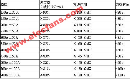
ITO layer optical, electrical, etching performance (etching solution: 600C 37% HCL: H267% HNO3 = 50: 50: 3): see Table 1-1.
Table 1-1
Chemical stability:
Alkali resistance is that after immersing in 600C and 10% sodium hydroxide solution for 5 minutes, the change of square resistance of ITO layer does not exceed 10%.
The acid resistance is that the ITO layer square resistance change value does not exceed 10% after being immersed in 250C and 6% concentration hydrochloric acid solution for 5 minutes.
The solvent resistance is that the change value of the square resistance of the ITO layer does not exceed 10% in the cleaning solution prepared by 250C, acetone, absolute ethanol or 100 parts of deionized water plus 3 parts of EC101 for 5 minutes.
Adhesion: After the tape is attached to the surface of the film layer and quickly peeled off, the film layer is not damaged; or after three consecutive tears, the ITO layer square resistance change value does not exceed 10%.
Thermal stability: In 3000C air, after 30 minutes of heating, the square resistance of the ITO conductive film should not be greater than 300% of the original square resistance.
Appearance Quality:
Crack: Not allowed.
Adhesives: including dust particles, broken pieces of glass and other protrusions, TN-type ITO conductive glass coating surface does not allow irremovable adherends with a height exceeding 0.1mm; STN-type ITO conductive glass coating surface does not allow irremovable Adhesions with a height exceeding 0.05mm.
Contamination: There should be no contamination that is insoluble in water or cannot be removed by general cleaning agents.
Edge collapse: length X width ≤2.0mmx1.0mm; depth does not exceed 50% of the thickness of the glass substrate; total length ≤5% of total side length.
Scratches: See Table 1-2. Table 1-2
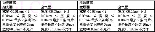
Vitreous linear defects (width W): including glass ribs and optical deformation are shown in Table 1-4. Table 1-4
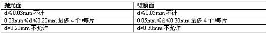
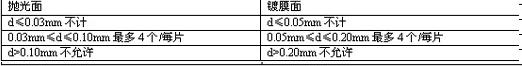
Point defects of the film layer: The point defects of the SIO2 barrier layer and the ITO conductive layer include pinholes, holes, particles, etc. The diameter of the point defects is defined as: d = (defect length + defect width) / 2. See Table 1-5. Table 1-5
Factory adaptive test method and judgment standard of ITO conductive glass:
size:
A. Test method: use a ruler and vernier caliper to measure the length, width and thickness of the original glass to be tested.
B. Judgment standard: The measurement result is qualified within the parameter range provided by the supplier.
Surface resistance:
A. Test method: The whole area of ​​the glass to be tested is used as the test area, and then the test area is divided into nine equal parts, and then the surface resistance of each area is tested with a four-probe tester.
B. Judgment standard: The average value of resistance and the dispersion value of resistance data are calculated according to the test results, and the result is qualified within the required range.
ITO layer temperature performance
A. Test method: heat the original glass to be tested in 3000C air for 30 minutes to test the surface resistance at the same point before and after heating.
B. Judgment standard: The square resistance value of the ITO conductive film should be no more than 300% of the original square resistance to be qualified.
Etching performance:
A. Test method: Put the original glass to be tested into the etching solution used in the production line to test its complete etching time.
B. Judgment standard: the time value of complete etching is less than half of the time set by the production process is qualified.
Or check according to the etching performance indicator in Table 1-1.
Alkali resistance of ITO layer
A. Test method: After placing the original glass to be tested in 600C and 10% sodium hydroxide solution for 5 minutes, test the surface resistance at the same point before and after immersion.
B. Judgment standard: The change value of the square resistance of the ITO layer does not exceed 10%.
Photoelectric performance and reliability:
A. Test method: According to the current production process parameters, the glass to be tested and the current production glass are selected to make a finished product and test its photoelectric and reliability performance;
B. Judgment standard: The photoelectric performance and reliability test results are equivalent to the current production glass results, and are within the scope of the test product model requirements.
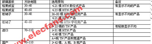
Selection rules of ITO conductive glass:
For products with modulus above 240, generally supplier B grade glass can be used;
For products with modulus above 40 and below 240, general grade A glass is generally used;
For products with modulus below 40, STN products generally use low resistance polished glass.
For COG products, 15 ohm polished glass is generally used. Attachment: Factory ITO glass reference selection principles:
6. How to use ITO conductive glass:
l No stacking is allowed at any time;
l In addition to the regulations, it is generally required to be placed vertically; try to keep the ITO face down when laying down horizontally; glass with a thickness of less than 0.55mm can only be placed vertically;
l Only four sides can be touched when picking and placing, not the surface of conductive glass ITO;
l Handle lightly and do not collide with other fixtures and machines;
l If you want to store for a long time, you must pay attention to moisture, so as not to affect the resistance and transmittance of the glass;
l For large-area and long glass, the float direction of the glass substrate should be considered when designing and typesetting.
7. Storage and handling methods of ITO conductive glass:
Storage method of ITO conductive glass:
ITO conductive glass should be stored at room temperature and dry under 65% humidity. During storage, the glass should be placed vertically. The glass should not be stacked more than two layers, and the wooden box ITO conductive glass cargo should not be stacked more than five layers. Cartons loaded with ITO conductive glass cargo cannot be stacked in principle.
ITO conductive glass handling method:
Fragile products should be handled with care to maintain stability during handling. The height of the floor should not exceed three layers during handling.
Through Floor Lift,Best Home Elevators,Wheelchair Lift For Home,Car Lift For Home Garage
XI'AN TYPICAL ELEVATOR CO., LTD , https://www.chinaxiantypical.com