In recent years, high-brightness LED applications have developed rapidly, especially in terms of signs and traffic lights. For automotive applications, LEDs also have great appeal. Long-life, shock-resistant, efficient, and good control of the light source are its advantages. Of course, compared to incandescent lamps, LEDs need drive circuits, and automotive electronics are powered by acid-lead batteries. They are mechanically driven alternators. These batteries are suitable for incandescent lamps and are not suitable for LEDs. Therefore, design is stable. A drive circuit with good voltage performance and low noise is very necessary.
This article refers to the address: http://
In theory, the LED light output is related to the drive current, independent of the supply voltage. For the most demanding applications, a resistor can limit the current if the supply voltage is stable. It is worth noting that for this simplest application circuit, LEDs exhibit self-stabilization characteristics to some extent. That is, if the temperature rises, the light output of the LED decreases, but at the same time its forward voltage drop also decreases, causing the drive current to increase, thereby compensating for the reduction in light output at higher temperatures. Unfortunately, the range of automotive power supply is very large, between 8V and 18V, the peak voltage can reach tens of volts. In addition, the high-brightness LED drive current is large, which generates a large amount of heat in the resistor, complicating the heat dissipation design.
A relatively simple solution is to use a linear buck regulator (Figure 1). D1 is a Zener diode and the current through the LED is set to VD1/RSET. D2 performs humidity compensation on the base diode. This circuit still has energy loss problems and resistance heat dissipation problems. This circuit is a cost-effective solution for low current LEDs, especially where the forward voltage drop of the LEDs in series is slightly lower than the supply voltage. 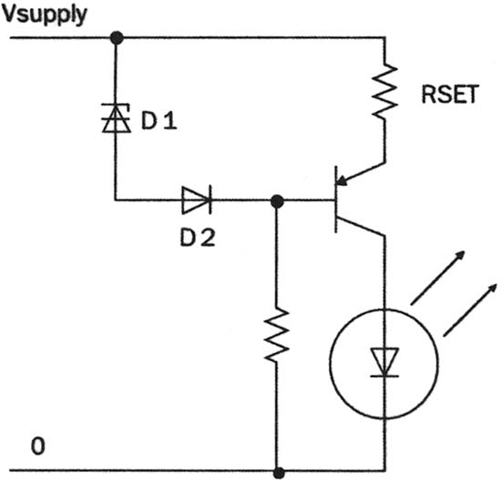
Figure 1 Simple steady current circuit
In most cases, switching power supplies provide a better electrical solution. As the name suggests, the switching power supply operates as a switch that charges the RLC circuit in one cycle; in the next cycle, the stored energy is used to drive the load. These circuits are extremely efficient, typically up to 90%. Switching regulators can boost voltage, lower voltage, and generate voltages of opposite polarity, which are not available with linear regulators.
The simplest switching regulator is the buck regulator shown in Figure 2. The voltage difference between the input voltage and the LED voltage charges the inductor L, and the current increases. When the current reaches a preset value, the control circuit The series connected transistors are turned off to form an alternating current in the LED path. Note that in LED driver applications, the switching regulator circuit controls the peak current. This value is set by the programmable IC or external component. The current value is also defined by the sense resistor on the drain of the FET switch. The current flowing through the LEDs of the buck regulator is continuous, but alternating, but not continuous to the power supply, which has a de facto effect on the power supply and increases the noise on the power line.
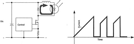
Figure 2 Step-down switching regulator circuit
If the supply voltage is lower than the sum of all LED series voltages, the boost regulator is used. The boost regulator (Figure 3) controls both the current and the voltage, and the circuit is relatively complex. The boost regulator also has serious interference problems at high currents. Therefore, the most stable and safe LED driver can be combined with step-up and step-down. A boost regulator can drive several buck regulators in parallel. In this way, the power supply is a good performance boost regulator, while at the load end is a high current output buck regulator.
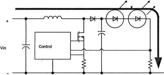
Figure 3 step-up switching regulator current circuit
All switching power supplies generate noise. The voltage regulator can increase the operating frequency. The output capacitor is filtered with a large capacitor. The LED power supply is of a constant current type. To reduce noise, the following measures must be taken:
· Reduce the working frequency.
• The switching transistor application is placed in the center of the board.
· Fast recovery diodes.
• Do not form a current loop in the LED area.
• Shorten cables and traces on printed circuit boards.
In addition to the above measures, the new solution also helps to reduce the noise of the drive power. Melexis' MLX10801 and MLX10803 LED drivers use a pseudo-random switching frequency generator to reduce electrical noise. Figure 4 is an example of a circuit for a low-noise application that complies with the CISPR25 Level 5 standard, where CISPR is the abbreviation for the International Committee on Radio Interference Special. The working inductance L1 should be determined based on the switching frequency and the LED current. To facilitate user design, the company also provides a software and Excel spreadsheet for selecting ROSC, RSET and RSENSE.
For the circuit of Figure 4, the switching frequency should be lower than 150KHz. If the LED current is between 0.5-1A, L1 and L2 are 100?H. The noise is broadband, so the filter capacitor uses a combination of large and small. Diode D1 is the primary source of high frequency noise and should be carefully chosen to use Schottky diodes when the supply voltage is below 100V.
The light output intensity of GaAs and GaAs PLEDs is closely related to the junction temperature. For example, if the LED outputs 100% at 25 ° C, it is only 80% at 80 ° C. The driver is equipped with a temperature slope compensation circuit. In fact, a PTC or NTC resistor can solve the problem, and the temperature coefficient of the PTC is used to balance the light output of the LED. To protect the LED, an NTC resistor can be added to the input of the device at temperatures above 80 °C.
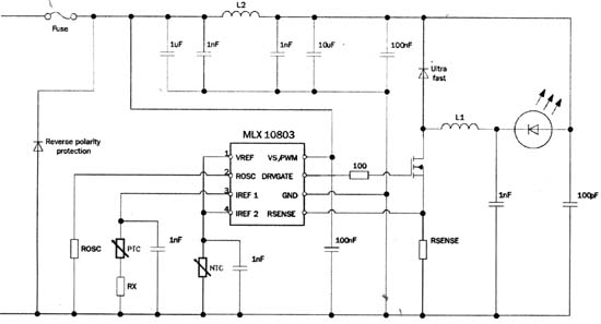
Figure 4 MLX10803 application example
Mini and nice looking, great powerful portable Battery Fan/ Usb Desk Fan.
Powerful - High quality motor, max wind speed 75ft/s, 3 speed (low, medium, high)
USB or Battery - Powered by USB or 2200mAh 18650 battery ( INCLUDED ), High quality battery, replaceable and rechargeable, 2.5~6 hours working time depend on different speed, USB charging
Very Compact - 13*3.3*9cm (5.1*1.3*3.5 inch), portability, handy, lightweight, easy to carry
Wide applications - Bring cool wind to you anywhere you go, you can also hang around your neck, Ideal for outdoors, camping, outside walking running, traveling, pool swimming, beach, car backseat, also can used at home and office, during studying/work/sleep, your desk, laptop, kitchen, and anywhere need cool wind.

Usb Clip Fan,Clip On Fan,Clip On Desk Fan,Small Usb Clip Fan
Shenzhen Hygea Technology Co.,Ltd , http://www.hygeaaromadiffuser.com