With the popularity of automobiles, the safety of automobiles has received more and more attention from people. After all, this is a major event concerning life safety. Nowadays, electric vehicles use electric windows, but there are still major safety hazards in electric windows. So far, many passengers have been reported to have been injured by the rising window, and most of the injured are children, so the electric window anti-pinch protection is proposed. The so-called electric window anti-pinch protection means that once the presence of an obstacle is detected during the automatic rise of the window, the window automatically stops moving upward to prevent damage to the obstacle; and moves downward to release the obstacle.
This article refers to the address: http://
The basic idea of ​​electric window anti-pinch can be summarized as follows: During the automatic rising of the window, the sensor detects the presence of an obstacle (including being caught or judging that there is an obstacle in the middle of the ascent). When an obstacle is detected, the drive motor reverses, causing the window to descend a distance and release the obstacle. The anti-pinch protection algorithm introduced in this paper is mainly realized by detecting the change of motor speed.
Motor cycle measurement
In the anti-pinch design, strictly speaking, the parameters involved should be the speed of the motor. However, in this subject, more specifically, it is not the rotational speed but the cycle. This topic uses the capture mode in the Timer module to detect the time interval between the falling edges of two pulses to obtain the period value. The longer the period, the slower the speed. Conversely, the smaller the period, the faster the speed. Therefore, from a functional point of view, the effect of the two parameters is consistent. In order to save the resources of the microcontroller, the direct cycle is used instead of the speed for anti-pinch detection.
The conversion calculation between the pulse period and the actual pulse period is:

The Timer is set to 16 prescaler and the reload value is 0000H, so its overflow period is 43ms and the resolution is 2.7ms.
In the period detection, the output pin of the Hall sensor is connected to the P3.4 port of the XC886. P3.4 is multiplexed into the input pin of the Timer21 pulse capture mode. In this topic, when the Hall sensor input is the falling edge of the pulse, the Timer generates an interrupt and calculates the period in the interrupt routine. The specific calculation process is as follows:
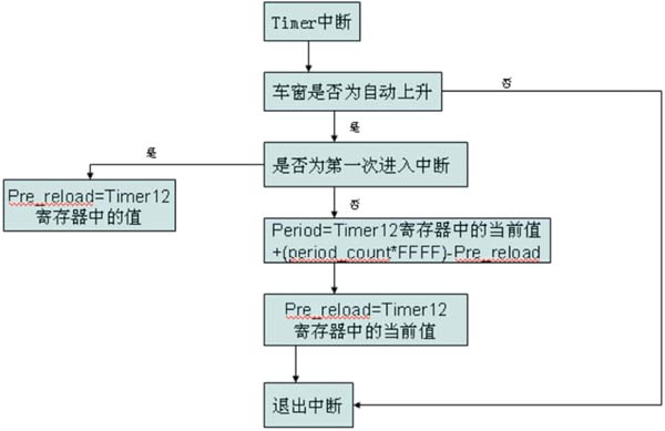
Figure 1 cycle calculation flow chart
Among them, Pre_reload is the value in the register when the previous pulse arrives, and the previous value is subtracted from the current value. It is worth mentioning that the period_count variable. When the timer overflows, period_count is incremented by one. This avoids cycle calculation errors due to timer overflow.
The specific implementation is: because it is only necessary to prevent the clip when the window automatically rises. So first determine if it is automatic rising. If it is automatically rising, it is judged whether it is the first time to enter the interrupt program. If it is the first time to enter the interrupt, the value in the current counter is stored in the variable Pre_reload. If it is not the first time, the value of the current counter is subtracted from Pre_reload. The value is used as the period value, and the current value is stored in Pre_reload. Used for the next time you enter the interrupt. This works every time an interrupt is entered until a stop command is received or the window reaches the top.
Determination of the position of the window
During the ascent of the window, due to factors such as the weight of the window and the resistance of the window frame, the cycle size at each position is different. Therefore, judging the position of the window is also very important. From a mechanical point of view, the rotation of the motor will drive the movement of the wire rope, thereby driving the upper and lower opening and closing of the window. Each time the motor rotates at a certain angle, the wire rope moves correspondingly for a certain stroke, so the stroke of the window movement is linear with the number of turns of the motor. The rotation of the motor causes the Hall sensor to generate a pulse signal, so the window position can also be measured by combining the Hall sensor with the timer module in the XC886CS. When the motor rotates one revolution, the timer Timer captures the falling edge of the Hall signal, thereby recording the position of the window in the interrupt service routine. Since the window may move up and down, the calculation of the window position cannot be performed only when the window is raised, and the corresponding adjustment should be made when the window is lowered. Therefore, after entering the interrupt service, the program first queries whether the state of the window is rising or falling. If it is rising, the position of the window will increase correspondingly every time the motor rotates; if it is down, the position of the window will decrease every time the motor rotates.
Proposal and Implementation of Anti-Pinch Window Algorithm
The anti-pinch algorithm used in this topic is based on the motor operating parameters. How to get accurate operating parameters, ie, the cycle, is the key to whether the anti-slip algorithm can be realized. The subject also optimizes the algorithm based on the algorithm found in the actual operation.
Anti-pinch test data analysis
In order to get the exact reference period and current value, we use the method of sending data through the serial port. Use the UART_vSendData8(ubyte ubData) statement in Keil C to send the period and current values, and use the serial port assistant software to receive the data.
When the window automatically rises, the data is sent to the display multiple times. Take out a good set of data, take the average, calculate the difference between the real-time value and the average value at each run, and then determine a suitable tolerance.
It can be seen from the value sent from the serial port that the pulse period of the rising window, that is, the rising speed of the window, after about 12 pulses from the bottom, basically rises linearly. Since the exact value of the pulse period at each point can be obtained by transmitting data through the serial port, the average value of the multiple test results can be taken for the period value at each point, and the average value is compared with the actual value of each test. It can be found that after the mean value of these values ​​is added with the tolerance of 1846, most of the actual running values ​​will be smaller than this value. Based on the consideration of the margin and the maximum clamping force, the final tolerance is 2000.
Proposal of anti-pinch algorithm
In the design of the algorithm, only the case of anti-clamping is carried out when the window automatically rises. In the other three cases (including manual window lift, manual window lowering, and automatic window lowering), no anti-pinch judgment is made. Because there is no problem of anti-pinch when the window is lowered, if there is an obstacle being clamped when the window is manually raised, the hand can be controlled to avoid being pinched. In the algorithm, the flag bits bWIN_Up_Down and bAutoFlag are used to indicate whether the window is automatically rising. If the controller obtains an automatic rising command, the two positions are. If these two digits are 1, then the anti-pinch judgment is made. It is also worth noting that, according to the experimental data, the voltage and pulse period values ​​of the three windows started from the bottom of the window are quite complicated and random, without any regularity, and at the bottom of the three pulsed window glass The total stroke will not exceed 1cm, so no anti-clamping will be carried out in this section.
The idea of ​​the algorithm is to store the reference period mentioned in the previous section in RAM. Then, the real-time period value of the motor running is detected during the automatic rising of the window, and the real-time value is compared with the reference value. If the difference between the two is more than three pulses, the obstacle is considered to exist. The window enters the automatic descent procedure and the window drops to the bottom. If no three consecutive pulses arrive or exceed the tolerance, then the obstacle is considered to exist and automatically rises to the top of the window.
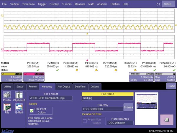
Figure 2 Cycle and current diagram in normal state
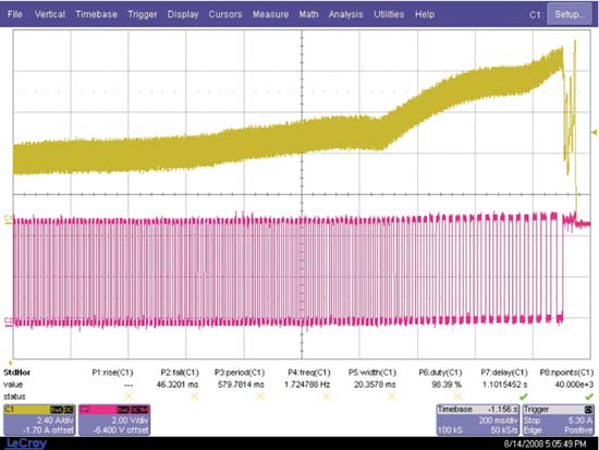
Figure 3 Cycle and current diagram of the clamping condition
Algorithm optimization
According to the problems existing in the actual operation of the algorithm, the algorithm must be optimized to obtain a better anti-pinch effect.
4.3.1 Algorithm optimization when the window is started at the bottom
According to the comprehensive analysis of the pulse period value, the change of the value is very unstable before the 12th pulse period, and the situation beyond the tolerance range often occurs. After this, the values ​​are basically within the established tolerance. Therefore, for the start of the bottom, the proposed solution is to filter out the first 12 pulse points, that is, no anti-clamping on the first 12 pulse points. The reason is that the first 10 pulse points are the bottom part of the window, and the window stroke is no more than 3cm, which will not have a big impact on the anti-pinch protection.
4.3.2 Algorithm optimization for window to top
It can be seen from the experiment that if the window rises normally, the window glass is the contact point between the window glass and the upper sash seal at the 209th pulse. After the window enters the upper sealing strip, the frictional force of the sealing strip will be different due to the difference in ambient temperature and air humidity, so there may be cases where the window cannot be normally closed.
Therefore, the solution can be solved by reducing the upper limit of the anti-pinch from the 223th pulse to the 208th pulse, that is, no anti-pinch is performed above the 208th pulse, and the following algorithm is performed according to the original algorithm. Anti-pinch.
4.3.3 Algorithm optimization when the window is stopped and restarted in the middle
The stop and restart of the window in the middle is the same as the bottom start. The difference between the two is that the bottom start will be large and outrageous in the first pulse, but the next few pulses will have a downward trend. Can give a tolerance, so that the two values ​​can be within the tolerance range, but stop and restart in the middle is a large number of consecutive outliers, and the size will occur with the position of the window and the length of the stop time. Change, so take different strategies for algorithm optimization.
When the window is activated, the first 8 pulses are ignored to shield the fluctuation of the pulse period due to the window start. After the masking, the anti-trap operation is still performed according to the algorithm. The 8 pulses are more reasonable values ​​obtained through repeated experiments. After 8 cycles, the period values ​​basically return to normal, within tolerance.
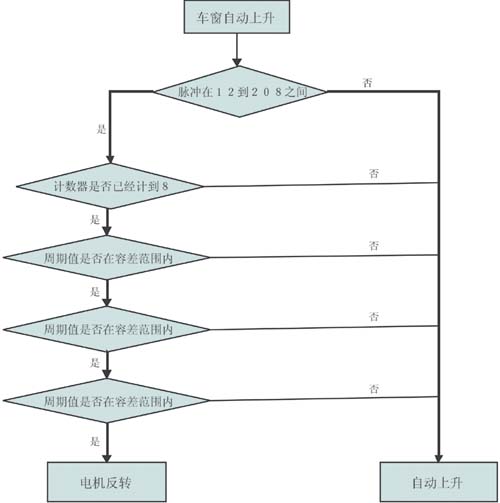
Figure 4 Optimized algorithm flow chart
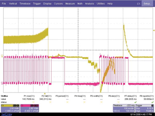
Figure 5 Cycle and circuit diagram of anti-pinch action
Summary of electric window anti-pinch
The anti-pinch algorithm used in this topic is discrete, not real-time, but only samples the period and current at a certain time. Because the sampling of the Hall sensor is not real-time. This method is suitable for microprocessors where computing power is not very strong and processing speed is not very fast.
This topic uses absolute anti-pinch, the detection period and current at each height, compared with the reference value, three times out of tolerance, it is considered that there is an obstacle, enter the anti-pinch treatment.
Stainless Steel Tube,Protection Tube,Stainless Steel Protection Tube,Astm 304 310 Stainless Steel Pipe
Thermocouple Wire,Thermocouple Connector Co., Ltd. , http://www.nbthermocouples.com