A bi-directional DC-DC converter (BDC) is a dual-quadrant operation of a DC-DC converter. Its input and output voltages have the same polarity, and the direction of the input and output currents can be changed. The BDC achieves bidirectional transmission of energy and is functionally equivalent to two one-way DC-DC converters, and is a typical "one-machine dual-use" device. In applications where two-way energy flow is required, the volume and weight of the system can be greatly reduced, which has important research value.
The in-depth study of the power electronic converter control model helps to optimize the converter design and improve converter performance. The literature [5-7] studied the control model of the converter and achieved good results. DC-DC converters need to constitute a closed-loop feedback control system to achieve regulated output and excellent dynamic performance. State-space averaging is a common method for analyzing switching regulation systems [8]. One-way DC-DC converters have mature control technologies, but different power flow control models are different in BDCs. Therefore, researching the control model of BDCs and proposing effective control schemes are important aspects of BDC research. This paper takes Buck/Boost dual-end time-sharing BDC as an example to analyze the control model of BDC.
2, BDC control model and PID regulator 2.1 application examplesFigure 1 shows an example of a solar array system [9]. In this system, Vb represents a battery and Isolar represents a solar cell. In the sunshine area, solar cells provide load energy while excess energy is charged by the BDC to the battery; in the shadow zone, the battery provides energy to the load through the BDC. The regulation point voltage Vo is maintained when the system is operating. In this system, the equivalent load of the converter in the dashed box appears as a dissipative type resistance during the solar shadow region, and as a power supply during the sunshine region, so its control model is different from the conventional inverter. Buck/BoostBDC can be divided into three types: Buck-type BDC, Boost-type BDC, and double-end time-controlled Buck/BoostBDC.
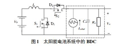
Figure 2 shows the equivalent circuit of a Buck-type BDC. Req is the equivalent load and represents both a dissipative load and a power supply.
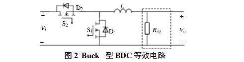
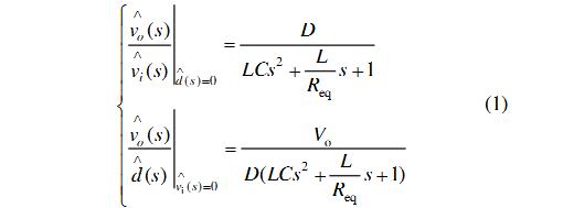
Set the duty cycle of S2 in Figure 2 as D:
Let the system parameters be: Vi=30~60V, Vo=24V, R=2.4 Ω, L=160μH, C=2000μF. When Req is a dissipative resistor, the circuit of Figure 2 is a conventional Buck converter. If there is no compensation link, the Bode diagram of the open-loop transfer function whose control is to output is shown in dotted line in Fig. 3(a). When the energy flows from Vo to Vi, Req is equivalent to negative resistance. At this time, Req=−2.4Ω in the transfer function (without compensation) from the control to the output, and two right-half plane poles appear in the open-loop transfer function of the system. The solid line in Fig. 3(a) corresponds to the Bode diagram. The amplitude-frequency characteristic curve is the same in both cases, and the phase-frequency characteristic curve is symmetrical to the 0° line. For the conventional buck converter, the system can have a certain amplitude and phase angle margin through the correction of the compensation link such as proportional (P), proportional integral (PI), and proportional integral derivative (PID). However, the buck converter with negative impedance load has two right-half plane poles. The phase-frequency characteristic curve approaches the 180° line after the resonance frequency, and the closed-loop system cannot be stabilized by the P or PI compensation.
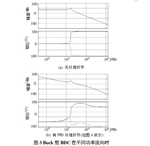
From the Nyquist stability criterion, the system is able to achieve system stability with two right-half-plane poles by crossing the π/2 line once. Differential (D) links can have phase compensation of π/4 for the system. Therefore, using PID compensation links may achieve closed-loop stability of the BDC system. This section uses the PID compensation link shown in Figure 4, through the rational design of PID parameters (R1 = 10kΩ, C1 = 47nF, R2 = 30kΩ, C2 = 33nF, R3 = 220Ω), can be obtained as shown in Figure 3 (b) The Bode plot from the control to the output (the dotted line corresponds to the dissipative load case, and the solid line corresponds to the source load case). The open-loop cut-off frequency is 1.28 kHz for both load conditions. The phase margin of the system under dissipative load is 64°, and the system phase margin is 51° when the source is loaded. The system has good stability.
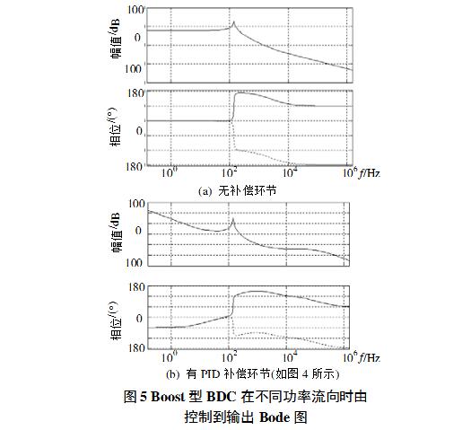
2.3 Boost type BDC control modelWhen the circuit Vi is voltage-regulated as shown in FIG. 2, it is a Boost-type BDC. Let S2 be the duty ratio in Figure 2.
The system power stage has a right half-plane zero. Figure 5(a) shows the Bode plot of a Boost-type BDC (the dotted line corresponds to the dissipative load case, and the solid line corresponds to the source load case). The system parameters are: Vo=20~30V, Vi=48V, R=10Ω, L=160μH, C=2000μF. It can be seen from the figure that the stability of the system (single closed loop) can only be achieved by differential (D) link compensation. Still use the PID compensation link shown in Figure 4 (parameters: R1 = 10kΩ, C1 = 47nF, R2 = 50kΩ, C2 = 20nF, R3 = 33Ω), Figure 5 (b) is the PID link compensation from control to output Bode Diagram (The dotted line corresponds to the dissipative load case and the solid line corresponds to the source load case). After being compensated by the PID link, the system is stable, and the open-loop cut-off frequency of the system is 1.15 kHz. In both cases, the phase margin is 47°, and the system has good stability.
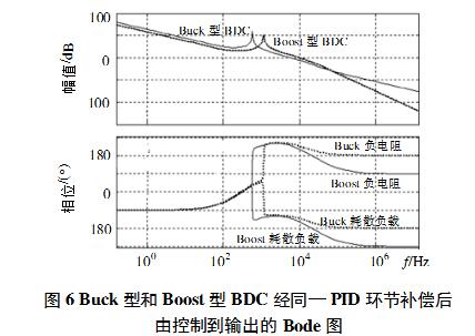
2.4 Buck/Boost Dual-Ended Time-Controlled BDC Control ModelIn the case of double-terminal time-sharing, the PID regulator designed is required to stably adjust the BDC in both directions. From the analysis of the control models of the above two types of BDCs, it can be seen that with the same PID regulator, the closed-loop stable operation of Buck-type BDC and Boost-type BDC can be realized. For the double-end time-stabilized BDC system analyzed in this section, the same PID link is used (parameter: R1 = 10kΩ,
C1=47nF, R2=20kΩ, C2=33nF, R3=270Ω) The compensated system Bode is shown in Fig.6. The dashed line is the case of Buck type BDC (the upper two of the phase-frequency characteristic curves are the source load conditions. The two are dissipative load conditions. The solid line is the Boost type BDC. The open-loop cutoff frequency of Buck-type BDC from control to output is
10.2kHz, phase angle margin for both dissipative load and source load is 48°; open-loop cutoff frequency for Boost-type BDC from control to output is 5.99kHz, phase angle under dissipated load and source load conditions The margin is 50° and the margin is 15.3dB.
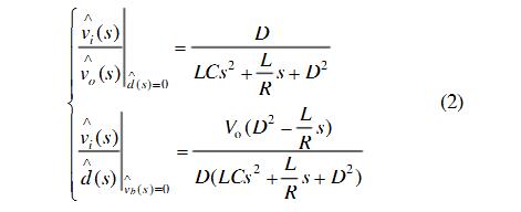
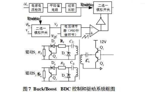
The specifications of the BDC prototype studied in this paper are as follows: 1 Auto-select voltage output according to power flow direction; 2 Low-voltage side: 15~30V (rated 24V); High-voltage side voltage: 30~60V (rated 48V); 3 Output power 300W. It is required to determine the voltage regulator side of the output voltage according to the direction of the power flow, that is, when the energy flows from Vo to Vb (refer to FIG. 1), the voltage is output from the Vb side and the control model is Equation (1); when the energy flows from Vb to Vo, Vo Side regulator output, control model for equation (2). The load in both cases is a dissipative type resistor. Design control circuit block diagram shown in Figure 7.
The control circuit uses a voltage regulator and a set of driving circuits to achieve voltage regulation at both ends of the Buck/Boost BDC, and automatically selects the voltage regulator terminal (Vo or Vb) according to the direction of energy flow.
Using the scheme of inductor current zero-crossing [1] and the parameters of the PID controller analyzed above, an experimental prototype was constructed.
(1) System stability test
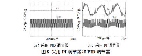
Figure 8(a) shows the output voltage waveform (coupled AC) of the prototype at the Boost side (48V) of the PID regulator. Figure 8(b) shows the output voltage waveform (coupled AC) on the 48V side when a PI regulator is used to obtain the same open-loop cutoff frequency, and the output voltage oscillates. The single-closed-loop PID regulator is implemented to achieve correct analysis of the two-way closed-loop stability.
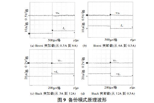
(2) Dynamic performance of the system Figure 9 (a), (b) are the sudden load (from 0.5A to 6A) and sudden discharge (from 6A to 0.5A) test waveforms at the 48V regulated output of the Boost side. (c), (d) are the sudden load (from 0.5A to 12A) and sudden unloading (from 12A to 0.5A) test waveforms at Buck-side (24V) regulated output. The 48V side response speed is 1.75ms, and the 24V side response speed is 0.6ms. The system has a fast transient response.
The bidirectional DC-DC converter has different control models when different power flows, and its voltage regulator needs to consider two energy flow direction factors. This article takes a Buck/Boost bi-directional DC-DC converter as an example to build a test platform. Through the analysis of bi-directional control model, it is considered that a single closed-loop regulator should adopt PID or other regulator with π/2 phase compensation. The stability and good dynamic performance of the test system indicates that the analysis in this paper is correct.
A30 3000 Puffs,Replaceable Atomizer Vape Battery,Relx Vape,Ignite Vape 3000
Lensen Electronics Co., Ltd , https://www.lensenvape.com