Expanding Optoelectronics is dedicated to answering your questions;
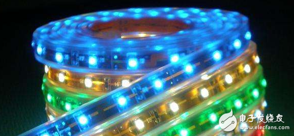
The principle of SMD LEDs is that the current exceeds a certain limit.
Should pay attention to the use
First, static protection1. The workbench of the contact LED light-emitting diode product should be covered with protective electrical tape and grounded reliably;
2. Personnel should wear an electrostatic wristband (preferably a wired electrostatic ring) and protective gloves when contacting the SMD LED. It is best to wear anti-static clothing, static shoes and an electrostatic cap when conditions permit.
3, the application of the process of contacting the LED equipment must be reliably grounded, such as: soldering iron, shearing machine, bending machine and welding equipment. It is also possible to install a plasma fan to eliminate static electricity;
4. In the use or when designing electronic circuits, the danger of excessive current to the LED must be considered.

1. SMD LED light-emitting diodes must be formed before soldering. The corners must be more than 3mm away from the gel to bend the bracket. The number of folding of the pin at the same position cannot exceed 2 times, the pin is bent at 90 degrees, and the original position is returned to 1 time;
2, the lead molding must be done with a fixture or by a professional, pay attention to avoid the first case of the epoxy body is too large to cause internal gold wire break; 3, the lead molding needs to ensure that the pin spacing is consistent with the circuit board;
4. When the SMD LED is in the process of soldering or soldered, please do not bend the lamp to avoid damage to the lamp.
Third, the patch LED light emitting diode installation method1. Do not install the LED with the pin deformed.
2. When installing the LED on the printed circuit board, the center distance of the hole on the circuit board should be the same as the center distance of the LED lamp foot. If the hole spacing is large, the lamp foot will have residual stress, and the resin part may be made during soldering. Deformation
3. When the chip LED light-emitting diode is inserted into the PCB board, the hole on the PCB board should match the size of the lamp pin to avoid being too large or too small;
4. It is recommended to use guide sleeve positioning when installing LED;
5, the double pin each solder pad pad area is not less than 4.6 square millimeters;
6. The area of ​​each solder fillet of the piranha is not less than 9.2 square millimeters;
7, SMD ordinary single crystal bracket each soldering pad area is not less than 3.9 square millimeters;
8, SMD three-in-one bracket each solder pad pad area is not less than 1.65 square mm;
9. Other types of lamps should be based on the actual lamp structure to determine the size of the pad.
1. Soldering iron soldering: soldering iron (up to 30W) tip temperature does not exceed 300 degrees, soldering time is less than 3 seconds, solder joint should be more than 3mm away from the colloid and it is recommended to solder under the card point;
2, dip soldering: welding temperature 260 degrees, dip soldering time not more than 3 seconds, dip soldering position at least 3mm from the gel, LED preheating temperature is 100-110 degrees, the longest does not exceed 60 seconds;
3. Since the LED chip is directly attached to the cathode holder, the pressure on the LED and the thermal shock to the wafer should be minimized during soldering to prevent damage to the wafer;
4. Do not apply any external force or vibration to the gel part of the LED during the soldering process or after soldering to prevent the gold wire from being disconnected. In order to protect the LED from the mechanical impact or vibration after soldering the LED light-emitting diode, measures should be taken to protect the gel until the LED Revert to room temperature;
5. In order to avoid damage to the LED light-emitting diode of the patch in order to avoid high temperature cutting, please cut the foot at normal temperature;
How should the design of the minimum LED circuit be carried out? Simple and clever LED driver circuitThe circuit directly uses 220V AC mains as the power source. Although the working current is not large, but the working voltage is high, and it is not isolated, so if you are interested in this circuit and want to make it, you must pay attention to safety.
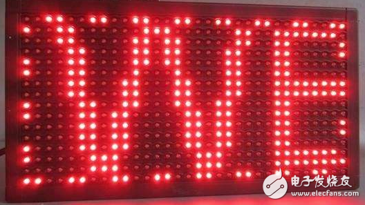
Such LED drive circuits are mostly used in lighting fixtures. Generally, it is the first gear of the lamp, LED gear position. Either an outdoor billboard or a simple LED bulb.
The circuit structure is clear and clear. The first is a bridge rectifier to rectify 220V AC into a pulsating DC with a frequency of 100Hz. The latter C1 filter capacitor filters the pulsating DC to a relatively stable DC of around 300V. 1300 in the figure is a high withstand voltage NPN transistor. The withstand voltage is at least 400V. The R1 resistor is the drive resistance of the triode. It is responsible for providing a base current for the triode to ensure the conduction of the triode. The R2 resistor is a current limiting resistor in the LED circuit that limits the maximum operating current and has a certain voltage divider to ensure proper operation of the circuit.
D1 is a 2V regulator. To be honest, this 2V regulator is really rare. Most commonly used Zener diodes are concentrated on 5.6V-12V. If you can't find a suitable 2V regulator, try diodes in series to get an analog voltage regulator. For example, a single diode with a voltage drop of 0.5V, then four ordinary diodes are 2V voltage drop. The C2 capacitor acts as a de-flashing in the circuit. Prevents LED flashing or stroboscopic conditions caused by changes in LED drive current caused by unstable voltages.
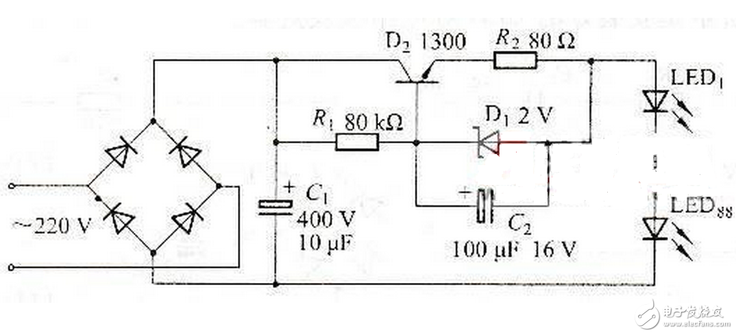
In the figure, the R2 resistor should be a resistor of not less than 2W. The specific model of the 1300 NPN transistor should be MJE13003. Its parameters are 400V withstand voltage, 1.5A maximum current and 40W maximum power. This triode is commonly found in energy saving lamp circuits. High voltage capacitors can also be found in energy-saving lamp circuits. The rear-level LEDs use white light straw hat LEDs. The number given in the figure is 88, and the number is still considerable. The brightness should be satisfactory.
Once again, self-made must pay attention to safety.So why is it clever? The clever thing is that D1 and R2 combined with the rear LED load form a constant current source. It can be seen that if the rear stage LED load is light, the triode will be powered by the 80K resistor, and the full power will supply power to the rear stage load, and the highest voltage will be output. If the LED of the latter stage is too hot due to heat, the voltage at the output of R2 will become lower, and the higher the current, that is, the heavier the load in the rear stage, the lower the voltage will become. When the voltage difference between the voltage and the base of the transistor is higher than 2V, the D1 regulator will conduct. Then, when the Zener diode is turned on, the driving current of the triode will be shunted. At this time, the conduction capacity of the triode will decrease, the output current capability will also decrease, and the current reaching the LED will also decrease. A function of automatically adjusting the operating current and maintaining the operating current is realized.
In circuit design, we hope that everyone can follow the principle of implementing the same or more functions with the fewest components. More than just cost savings, the key is to apply components with maximum efficiency, reduce the failure point of the entire circuit, and ensure the stability of the circuit.
Written at the end, if some of the texts are incorrectly explained or you have a more detailed explanation, you can write them directly in the comments.

Shenzhen Esun Herb Co.,Ltd. , https://www.szyoutai-tech.com