Why do digital engineers need RF knowledge?
In many high-speed applications such as computers, communications, etc., many digital buses have data rates of Gb/s or higher. Traditionally, we believe that the ideal digital signal of 0, 1 begins to show more of its RF characteristics. Real digital signals are increasingly exhibiting the characteristics of their microwave circuits during transmission.
In the analysis of these high-speed signals, the traditional time domain analysis method faces the problems of insufficient precision and lack of analytical methods, and the frequency domain analysis method in the RF microwave field is very mature and perfect. Therefore, the analysis and measurement of high-speed digital signals are increasingly beginning to adopt some RF or microwave analysis methods. Digital design engineers need to use more RF methods or concepts to analyze digital signals, such as using frequency domain analysis of the spectrum of the signal, and S-parameters to analyze the reflection and loss of the transmission path.
In order to help the majority of digital test engineers understand the basic concepts of frequency domain analysis, I have specially compiled this article "The RF knowledge that digital engineers need to master". This article was first published at the 2013 EDI CON conference. Come out and share with everyone.
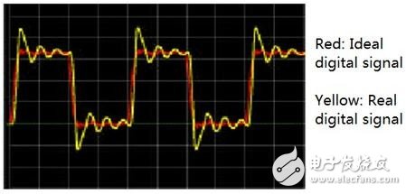
The primary reason for the analysis of digital signals is that the real-time transmission of high-speed digital signals is far from the ideal 0/1 level in textbooks. There must be some (even very serious) distortion and distortion in the actual digital signal transmission process. As shown in the figure below, red is the ideal digital signal waveform we expect, while yellow is the real signal waveform. It can be seen that the signal has been greatly deformed due to oscillation (usually due to poor impedance matching). In fact, in the case of high speed, this is already a good signal waveform. In many cases, the waveform of the signal will be worse than this.
To carry out research on digital signals, it is first necessary to obtain a true digital signal waveform, which involves the use of measuring instruments. The best tool for observing the waveform of an electrical signal is an oscilloscope. When the signal rate is high, the oscilloscope bandwidth is generally higher. If the oscilloscope used is not bandwidth-intensive, the high-frequency components in the signal will be filtered out and the observed digital signal will be distorted. Many digital engineers are accustomed to using harmonics to estimate signal bandwidth, but this method is less accurate.
For an ideal square wave signal, its rising edge is infinitely steep. From the frequency domain, it is composed of an infinite number of odd harmonics. Therefore, an ideal square wave can be considered as an infinite number of odd-order sinusoidal harmonics. Superimposed.

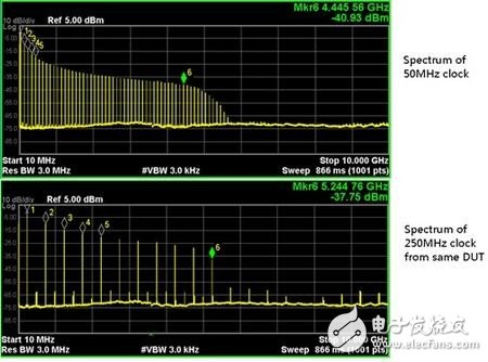
But for a real digital signal, its rising edge is not infinitely steep, so the energy of its higher harmonics is limited. For example, the following figure shows the spectrum of 50Mhz and 250MHz clock signals generated by the same clock source. We can see that although the output clock frequency is different, the main spectrum energy of the signal is concentrated within 5GHz, and the spectrum of 250MHz is not seen. The distribution must be five times larger than 50MHz.
For real data signals, the spectrum is more complicated. For example, the envelope of the spectrum of a pseudo-random sequence (PRBS) code stream is a sinc function. The following figure shows the spectrum of 800 Mbps and 2.5 Gbps PRBS signals generated by the same transmitter. We can see that although the output data rate is different, the main spectrum energy of the signal is concentrated within 4 GHz, and 2.5 Gbps is not seen. The high frequency energy of the signal is much higher than 800Mbps.
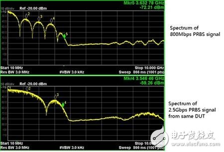
The two figures above are all measured by means of a spectrometer. Although modern digital oscilloscopes already have digital FFT capabilities to help users observe the signal spectrum, spectrum analyzers are still the most accurate tool for analyzing the frequency distribution of signal energy due to the limitations of ADC bits and dynamic range. The digital engineer can analyze the spectral distribution of the digital signal under test by means of a spectrum analyzer. When no spectrum analyzer is available, we usually estimate the spectral energy of the signal under test based on the rise time of the digital signal.
Maximum signal frequency content = 0.4/fastest rise or fall TIme (20 - 80%)
Or
Maximum signal frequency content = 0.5/fastest rise or fall TIme (10 - 90%)
From the previous research, we know that the spectrum of digital signals is widely distributed, and the highest frequency component range depends mainly on the rise time of the signal and not just the data rate. When such a high-bandwidth digital signal is transmitted, the first challenge is the impact of the transmission channel.
The true transmission channel, such as PCB, cable, backplane, connector, etc., has a limited bandwidth, which will weaken or completely filter out the high-frequency components in the original signal, and the high-frequency components will be lost on the waveform. That is, the edge of the signal is slowed down, and overshoot or oscillation occurs on the signal.
In addition, according to Faraday's law, a varying signal transition creates an eddy current within the conductor to counteract the change in current. The faster the rate of change of current (the shorter the rise or fall time of the signal for a digital signal), the stronger the eddy current in the conductor. When the data rate reaches above about 1 Gb/s, the current and the induced current in the conductor are substantially completely offset, and the net current is only limited to flow on the surface of the conductor, which is the skin effect. The skin effect increases the loss and changes the impedance of the circuit. The change in impedance changes the phase relationship of the harmonics of the signal, causing distortion of the signal.
In addition, the FR-4 medium most commonly used to make circuit boards is woven from glass fibers, and its uniformity and symmetry are relatively poor. At the same time, the dielectric constant of FR-4 material is also related to the signal frequency, so the signal The transmission speeds of different frequency components are also different. The difference in transmission speed further changes the phase relationship of each harmonic component in the signal, thereby making the signal worse.
Therefore, when a high-speed digital signal is transmitted on a PCB, the high-frequency component of the signal is weakened due to loss, and different frequency components are transmitted at different speeds and superimposed at the receiving end, and at the same time, a part of the energy Multiple reflections occur at impedance discontinuities such as vias, connectors, or line width variations, and combinations of these effects can severely alter the shape of the waveform. It is a big challenge to analyze such a complex problem.
It is worth noting that many factors such as the amplitude attenuation of the signal, the change of the rise/fall time, and the change of the transmission delay are related to the frequency components, and the effects of different frequency components are different. For digital signals, the frequency component is related to the digital symbols transmitted in the signal (for example, the code stream of 0101 and the code stream represented by 0011 are different), so different digital code streams are received in transmission. The impact is different. This is inter-symbol interference (ISI).
Wire Feeding Roller is part of the spraying system.
Wire Feeding Roller
Wire Feeding Roller,Welding Wire Feed Roller,Wire Feeder Roller,Wire Feed Drive Roller
Shaoxing Tianlong Tin Materials Co.,Ltd. , https://www.tianlongspray.com