The two passbands of the filter are generated by odd and even modes, respectively, and have three transmission zeros with an interpolated loss of 0.76 dB/1.13 dB and an in-band reflection of -19.2 dB/-15.1 dB, respectively. In 3.75~7.33 GHz, the attenuation is below -20 dB, which has high selectivity and wide stopband characteristics, and the measured results of the filter are in good agreement with the simulation results. The dual-mode filter has a very small size of 14.03 mm & TImes; 31.48 mm, which is 0.15 λg & TImes; 0.34 λg, so this solution is very useful in the engineering field.
0 Preface
With the rapid development of modern wireless communication technology, communication systems operating in two or more frequency bands have become an important direction of wireless communication research. Therefore, multi-frequency microwave components are one of the research hotspots in recent years, which drives multi-frequency. The development of filter technology. For example, wireless local area network (WLAN) and broadband interoperability microwave access (WiMAX). The current WLAN works mainly at 2.45 GHz (2.4~2.484 GHz), 5.2 GHz (5.15~5.35 GHz) and 5.8 GHz (5.725~5.825 GHz), while WiMAX works at 2.5 GHz (2.5~2.69 GHz), 3.5 GHz (3.4). ~3.69 GHz) and 5.5 GHz (5.25~5.85 GHz). On the other hand, multi-band filters with miniaturization, low cost, and ease of fabrication have become one of the most important circuit components in modern wireless communication systems.
The microstrip dual-mode filter has a simple structure, small size, light weight, low cost, easy integration, low insertion loss, and inherent order is half the order of the conventional filter, which can reduce the size and make the structure more compact. Therefore, it has been widely used in satellite communication and wireless communication, and has attracted the attention and attention of many researchers. In the 1970s, Wolff first proposed and designed the first microstrip dual-mode filter. Since then, people have begun research on microstrip dual-mode filters, which play an important role in the field of filters.
In this paper, a novel dual-mode dual-passband filter design for WLAN/WiMAX is proposed. Based on the symmetrical T-type open-circuit branch loading dual-mode resonator, the odd-even mode principle is analyzed first. The electric field distribution and current distribution of the dual-mode resonator are analyzed. Finally, a dual-passband filter for WLAN and WiMAX frequency bands is designed. The center frequencies are 2.4 GHz and 3.5 GHz respectively, and the coupling principle is applied. Analysis and analysis of the effect of coupling spacing on bandwidth. Finally, the measured results are very good. Three transmission zeros are generated outside the band, and the upper stop band has better out-of-band rejection. The final simulation and experimental measurements are in good agreement and have good consistency.
1 Symmetrical T-type open-circuit branch loading analysis
The symmetrical T-type open-circuit branch-loaded dual-mode resonator proposed in this paper is composed of a half-wavelength step-impedance resonator and two symmetrical T-shaped open branches. The specific structure is shown in Fig. 1(a).
Since the structure has a symmetrical characteristic with respect to the plane of symmetry AA', the classical odd-even mode analysis method can be used to analyze the resonant frequency of the resonator. According to the dual mode resonator model, this structure has two resonance modes, an odd mode resonance mode and an even mode resonance mode.
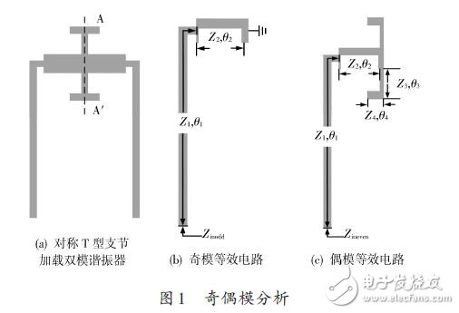
When excited by the odd-mode voltage source, the symmetry plane is the electric wall, and the voltage of the symmetry plane AA' is zero, which is equivalent to the short-circuit state, and the corresponding equivalent circuit is shown in Fig. 1(b).
When excited by the even mode current source, the symmetry plane is the magnetic wall, and the current at the symmetry plane AA' is zero, equivalent to the open state, and the corresponding equivalent circuit is shown in Fig. 1(c).
When the resonator discontinuity is ignored, the input impedance Zinodd at odd-mode excitation can be expressed as:

Its resonance condition is Zinodd = ∞. It can be seen from equation (1) that the odd-mode resonant frequency is only related to θ1, θ2, Z1, Z2, and is independent of the intermediate symmetric T-shaped open-section branch. Similarly, when the even mode is excited, the resonant frequency of the even mode can be obtained related to the intermediate T-shaped open branch. When the structure of the intermediate symmetric T-shaped open branch changes, the resonant frequency of the even mode will change accordingly. There is no effect on the resonant frequency of the odd mode.
Figure 2 shows the electric field distribution of the odd and even modes of the dual mode resonator.
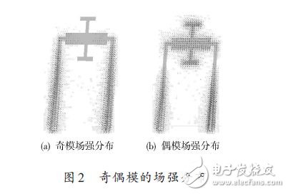
As shown in Fig. 2(a), the electric field distribution of the odd mode is mainly distributed on the left and right sides of the stepped impedance resonator, and is symmetrical. However, there is no field strength distribution in the symmetrical T-shaped open branch, which is obviously independent of the branch loading.
Similarly, as can be seen from Fig. 2(b), both the stepped impedance resonator and the symmetrical T-shaped branch are distributed with an electric field, and the electric field is symmetrical about the plane of symmetry AA', which is the electric field distribution of the even mode. Therefore, the symmetrical T-branch does not affect the odd-mode resonant frequency, only the even-mode resonant frequency.
Figure 3 shows the current distribution of a symmetric T-joint loaded resonator.
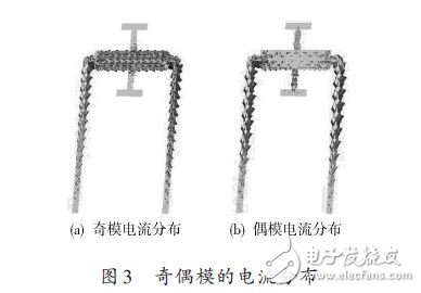
As shown in Fig. 3(a), the surface current is mainly distributed on the left and right sides of the step resonator. The current flows from the right branch to the left branch, and the symmetrical T-joint has no effect on the odd mode. The current distribution characteristics of the mode.
Figure 3(b) shows the current distribution of the even mode, and the entire dual mode resonator has a current distribution. It can be observed from the figure that current flows from the two T-shaped branches into the stepped impedance resonator, then to the branches at both ends, and is symmetric about the plane of symmetry AA'.
2 filter design example
In order to verify the above theoretical analysis, a dual-mode dual-passband filter for WLAN/WiMAX was designed using the dual-mode resonator discussed in the paper. The design specifications of the filter are: the first passband has a center frequency of 2.4 GHz and is applied to the WLAN band; the second passband has a center frequency of 3.5 GHz and is applied to the WiMAX band; the in-band insertion loss is less than 1 dB, and the in-band The return loss is -20 dB, and the suppression is greater than 20 dB in the upper stop band of 3.8~6.9 GHz. The dielectric plate used has a dielectric constant of 2.2, a thickness of 0.508 mm, and a loss tangent tan δ = 0.000 9, The thickness of the copper foil is 0.018 mm.
Xinxiang Mina Import & Export Co., Ltd. , https://www.mina-motor.cn