The whole system consists of AT91RM9200 processor, CMOS sensor, audio acquisition system, Ethernet power supply system and Ethernet data communication. Firstly, the image is captured by the CMOS sensor lens, and the audio can be collected at the same time. After being processed by the AT91RM9200 processor, the whole process transmits data through the network and supplies power through the network, thereby realizing the function of the network-powered network camera system.
2 system hardware design
2.1 AT91RM9200 related design
The AT91RM9200 embeds the ARM920T ARM Thumb processor core, which operates at 180 MHz with performance up to 200 MIPS, memory management unit SRAM of 16K, and ROM of 128K. The AT91RM 9200 integrates many standard interfaces, including USB 2.0 full-speed host and device ports, most peripherals, and the 10/100 Base-T Ethernet Media Access Controller (MAC), which is widely used at the network layer. In addition, it offers a range of industry-standard peripherals for use in audio, telecom, flash card infrared and smart cards.
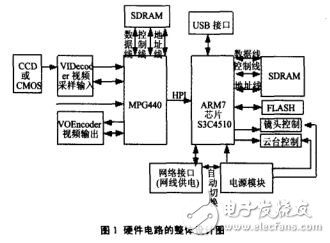
Independent Media Interface (MII) or Simplified Independent Media Interface (RMII) with integrated 28-byte FIFO and dedicated DMA channels for receive and transmit. Automatic protocol control and fast automatic data transmission are compatible with MMC and SD memory cards, supporting two SD memories and 32-bit high-speed data stream transmission. The hardware structure of the system is shown in Figure 1.
As the CPU of the system, AT91RM9200 uses MT9D131 as the image acquisition sensor. The MT9D131 is a CMOS sensor with a 2 megapixel image sensor chip that is widely used in the surveillance industry because of its better performance. Capturing the microphone's audio signal and processing it with the WM8731, the WM8731 is a low-power, high-quality audio encoder/decoder with integrated headphone driver designed for portable digital audio applications. The device provides CD-quality audio recording and playback, providing 50 mW of output power for a 16 Ω load. In addition, the AT91RM9200 has a wealth of peripherals and I / O, which also provides great convenience for future system upgrades.
2.2 POE power supply design
2.2.1 Working Process of POE Power Supply
First, the PSE device outputs a small voltage on the port until it detects that the cable terminal is connected to a powered-end device that supports the IEEE802.3af standard. After detecting the powered device PD, the PSE device may classify the PD device and evaluate the power loss required by the PD device.
POE technology allows safe and reliable transmission of 48 V power up to 15 W over existing Category 5, Category 5 and Category 6 networks, making it ideal for communications applications. It can power IP phones, WLAN access points, network cameras and other types of network terminals in the range of 13 W (measured by powered devices). The schematic diagram of POE power supply is shown in Figure 2.
2.2.2 Power over Ethernet Controller LTC4269
Linear Technology has introduced the IEEE802.3af Power over Ethernet (POE) controller LTC4269, which features an integrated switching regulator that greatly simplifies the design of powered devices (PDs). The LTC4269 enhances traditional POE functionality.
The user can configure a stepped load current representing the PD power rating, a rugged 100V hot-pull MOSFET that isolates the Power over Ethernet DC/DC converter during detection and classification while providing 100 mA of inrush current when using any PSE It can smoothly power up the transition.
3 system software design
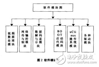
The software system consists of the system bootloader, the embedded operating system, and the upper application. Most bootloaders contain two different modes of operation: bootloading and downloading. The boot load mode is also called autonomous mode, that is, the bootloader loads the operating system from the storage device on the target machine into the RAM, and the entire process has no user intervention. In the download mode, the bootloader on the target machine will download files from the host through a serial port connection or a network connection.
The software system also includes the key TCP/IP and UDP protocol libraries of the network camera. Application software includes file system management, network services, mail delivery, file transfer, and detection of alarms. The network service program sends voice and images to a port on the network for access by other network devices.
U-Boot migration process: U-Boot source code can be downloaded from the official website. Install the cross compiler in Linux, compile the code, and generate the U-Boot.bin file. Displayed after startup. code show as below:
DRAM ConfiguraTIon:
Bank#0 16 MB
Flash: 16 MB
In:serial
Out:serial
Err:serial
Hit any key to st op autoboot:0
K9Uboot
Conclusion
This paper introduces the design and implementation of the network camera with AT91RM9200 processor as the core. The network power supply module LTC4269 enhances the traditional POE function DC/DC controller. The CMOS sensor MT9D131 realizes image acquisition, and its powerful image acquisition capability ensures clear and reliable dynamic images.
The audio codec WM8731 can realize the acquisition of camera audio. At present, the AT91RM9200 has a wide range of applications in consumer electronics such as audio/video, voice and multimedia. Therefore, the system has a good application prospect.
find out ceiling fan according to the blade quantity, different blade makes different style
Ceiling Fans,Intelligent Ceiling Fans,Flushmount Smart Ceiling Fan,Large Intelligent Ceiling Fans
Jiangmen MagicPower Electrical Appliances Co.,Ltd. , https://www.magicpowerfan.com