With the continuous advancement of modern society, people are increasingly unable to leave the car. However, with the rapid increase in the number of cars, road safety has attracted more and more attention. It is now recognized that it is unrealistic to rely solely on the structural factors of the car itself to ensure safe driving. Therefore, it is necessary to strengthen the main parts of the vehicle that are involved in safety, conduct regular inspections, and apply their technical status according to certain technical standards. The assessment is carried out, and the data obtained by various test benches with certain precision are used to scientifically and quantitatively judge the technical status of the vehicle safety device and give an appropriate evaluation. The failure rate of the car lamp is relatively high during the driving process of the car. When the lamp is faulty, the driver's awareness of the car driver cannot be correctly reflected and the accident is hidden in the safe driving.
With the wide application of electronic systems in automotive products, the automation of control systems is greatly guaranteed, and the shape of automobiles is becoming more and more streamlined. The taillights of automobiles have a great effect on the perfect embodiment of the overall shape of automobiles. The taillight control system of automobiles is in the finished products of automobiles. The proportion is also gradually increasing.
The taillights are the best embodiment of the car brand. The shape of the different taillights, the installation position on the car, and the relative position of different signal functions are all effective means to make the car unique. At the same time, for the whole car, after the taillights are installed, they must be integrated with the body, and have overall coordination when lighting and unlit. The products of domestic automobile taillight control technology are mainly the taillights of the car with dynamic graphic display.
The subject researched and developed in this paper is the circuit design of the automotive taillight controller, which is based on the AT89S52 chip produced by Intel Corporation. In this system, the basic working condition of the taillights of the car is displayed by 8 LEDs. The research and development of the vehicle taillight control system not only greatly improves the advanced nature of the car, but more importantly, reduces the possibility of traffic accidents.
Hardware design and working principle
The system hardware mainly includes the following three modules: logic switch controller, AT89S52 single-chip system, LED light array, etc., thus forming three modules of signal recognition circuit, controller and lighting circuit. The single-chip microcomputer system (microcontroller) acts as a central processing unit, and according to the logic switch controller, detects the switch control signal executed by the driver, and the corresponding signal obtained is transmitted, so that the single chip system receives the command, thereby causing the LED light array to issue corresponding instructions. . The overall design of the system is shown in Figure 1.
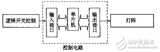
Figure 1 system overall design
among them:
1) The logic switch controller consists of five switches, which are left turn, right turn, check, night drive, reset, etc.
2) The MCU system is a 40-pin AT89S52 chip, of which 19 are used.
3) The lamp array is L4L3L2L1R1R2R3R4 from left to right, wherein the lamp array R1R2R3 represents the three indicators on the right side, L1L2L3 represents the three indicators on the left side, and R4L4 represents the nighttime driving time.
The control functions of the designed taillight control system of this design include left turn, right turn, brake check, night driving, etc., mainly to simulate the actual taillight control circuit of the car, so as to achieve high reliability, good practicability and universality. The hardware circuit of the research solution is simple and can be widely applied to various motor vehicles. The system circuit diagram is shown in Figure 2.
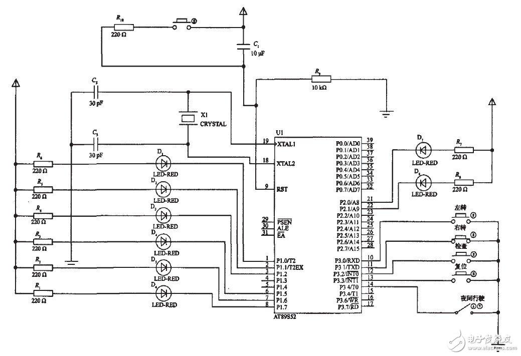
Figure 2 system circuit
The working principle of the system is: after the left turn switch is triggered, the MCU receives the signal and processes it. At this time, the L1L2L3 lights up in the left cycle; when the right turn switch is triggered, the R1R2R3 lights up in the right cycle; When triggered, L3L2L1R1R2R3 flashes at the same time; when the reset switch is triggered, the left turn, right turn and check are all cleared, that is, L3L2L1R1R2R3 does not work; when the night travel switch is closed, R4L4 is bright, and the other four states can also be get on. (Note: D1D2D3D7 is L1L2L3L4 and D4D5D6D8 are respectively R1R2R3Rt4).
software design
After analyzing the working principle of the taillight control system of Figure 1, the software of this design is mainly composed of main program, keyboard scanning subroutine, delay subroutine and other modules, and is written in C51 language.
As can be seen from Figure 2, the single-chip microcomputer adopts AT89S52, and its P1.O~P1.2 port and P1.5~P1.7 port in P1 port and P2.0 port and P2.1 port in P2 port are used for LED light output control. The P3.0~P3.4 port is a flashing mode control switch, the current limiting resistor 220, the LED current is about 10 mA, and a 12 MHz crystal oscillator is used.
1 main program
The main program mainly completes hardware initialization, subroutine call and LED display function. The main program flow chart is shown in Figure 3.
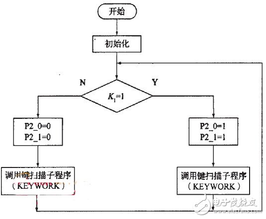
Figure 3 main program flow
Solar Flood Lights For Trees,Brightest Solar Flood Lights,Commercial Grade Solar Flood Light,100W Solar Flood Lights
Jiangmen Biaosheng Solar Energy Technology Co., Ltd. , https://www.bsprosolar.com