The emergence of the emerging field of semiconductor lighting has made engineers who specialize in three areas of power electronics, optics and thermal management (mechanical engineering) a sought-after talent. At present, there are not many engineers with experience in three fields, and this usually means that the background of the system engineer or the overall product engineer is related to these three areas, and they also need to cooperate with engineers in other fields as much as possible. System engineers often bring their habits or accumulated experience in the original field into the design work, which is similar to what an electronic engineer who mainly studies digital systems turns to solve power management problems: they may rely on Simple simulation, do not directly test the power supply on the test bench, because they do not realize that the switching regulator needs to carefully check the layout of the board; in addition, if it has not passed the test bench test, the actual work situation It is difficult to match the simulation.
In the process of designing LED luminaires, when the system architecture engineer is an electronic power expert, or the power supply design is contracted to an engineering company, some common habits in standard power supply design will appear in the LED driver design. Some habits are useful because LED drivers are very similar in many ways to traditional constant voltage sources. Both types of circuits operate over a wide range of input voltages and large output power. In addition, these two types of circuits are connected to different connections such as AC power, DC regulated power rails or batteries. The challenge.
Power electronics engineers are accustomed to always want to ensure high accuracy of output voltage or current, but this is not a good habit for LED driver design. Digital loads such as FPGAs and DSPs require lower core voltages, which in turn require tighter control to prevent higher bit error rates. Therefore, the tolerances of digital power rails are usually controlled within ±1% or less than their nominal values, and can also be expressed in absolute values, such as 0.99V to 1.01V. When introducing the design habits of traditional power supplies into the field of LED driver design, the usual problem is that in order to achieve tight control of the output current tolerance, more power will be wasted and more expensive devices will be used, or both. It.
Cost pressure
The ideal power supply is not expensive, the efficiency can reach 100%, and it does not take up space. Power electronics engineers are accustomed to listening to customers, and they will do their utmost to meet those requirements in an effort to design the system within the smallest space and budget. In the LED driver design is no exception, in fact it faces greater budget pressure, because the traditional lighting technology has been fully commercialized, and its price has been very low. Therefore, it is very important to spend every penny under the budget. This is also the place where some power electronics designer engineers are "introduced" by old habits.
Controlling the accuracy of the LED current to the same accuracy as the supply voltage of the digital load wastes both power and cost. 100mA to 1A is the current range for most current products, especially the current 350mA (or, more precisely, the current density of the optoelectronic semiconductor junction is 350mA/mm2), which is a compromise between thermal management and lighting efficiency. The integrated circuit that controls the LED driver is silicon-based, so there is a typical bandgap in the 1.25 V range. To achieve a 1% tolerance at 1.25V, a voltage range of ±12.5mV is required. This is not difficult to achieve, and a variety of low-cost voltage reference circuits or power control ICs that can achieve such tolerances or better tolerances are inexpensive. When controlling the output voltage, a high-precision resistor can be used to feed back the output voltage at very low power (as shown in Figure 1a). In order to control the output current, some adjustments need to be made to the feedback mode, as shown in Figure 1b. This is the only and simplest means of controlling the output current.
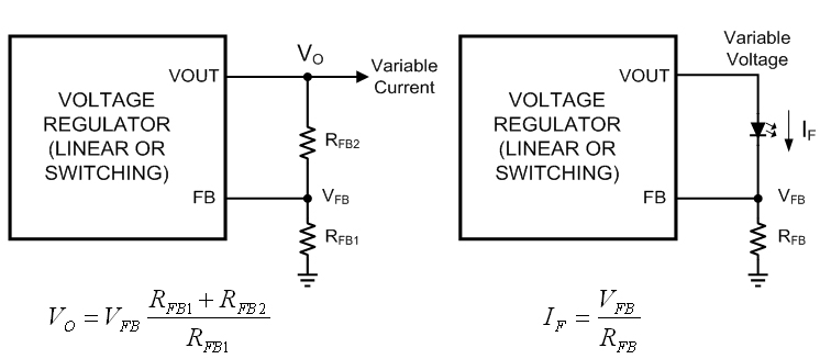
Figure 1a: Voltage feedback; Figure 1b: Current feedback
After in-depth research, one of the main drawbacks of this approach is that the load and feedback circuits are identical. The reference voltage is applied to a resistor in series with the LED, which means that the higher the reference voltage or LED current, the greater the power consumed by the resistor. Therefore, the reference voltage of the first generation of dedicated LED driver ICs is much lower than that of current products, which is similar to battery chargers. Lower voltage means lower power consumption, which means smaller, cheaper, lower loss current sense resistors. In the simple low-end feedback environment shown in Figure 1b, 200mV is a conventional voltage selection. However, to achieve a ±1% tolerance at a 200mV reference voltage, a very expensive integrated circuit is required, with a tolerance of ±2mV relative to the nominal reference voltage. Although this is not impossible, higher accuracy requires higher costs. The ±2mV tolerance requires the production, test, and binning techniques required for high-precision voltage references, where additional cost should be spent on smarter LED drivers. The value of the new cost is the addition of a feedback loop with which the light output (rather than the current output) can be used to control how the LED is driven.
Measuring light output
Just as digital product designers take simulations to solve problems when they encounter uncertainties in power supply design, system architects from power electronics engineers think of high-precision outputs when designing LED luminaires. LED manufacturers have made it clear that the luminous flux is proportional to the forward current. With the same current driving all the LEDs, each LED produces the same luminous flux. Therefore, the power electronics engineer will conclude that high precision current is a must. In this way, they forget that the lumens and lux values ​​of the light output (instead of the amperage) are the focus. Measuring current is easy, and in contrast, measuring light requires expensive large equipment, such as the integrating sphere shown in Figure 2, and most electronics engineers don't know much about the integrating sphere.
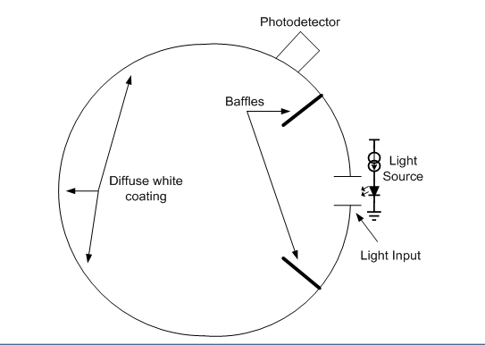
Figure 2: Optical integration sphere cross-section
In addition, even a current source with a tolerance of ±0.1% (which would be quite expensive) has great market value, and it has no effect on producing a strict tolerance value in the actual light output. This can be determined by observing the binning of the LED luminous flux. Table 1 shows the luminous flux binning results for the high-end cold white LEDs of the world's top three power optoelectronic semiconductor manufacturers at 350 mA and 25 °C. Note that the last column is the tolerance average for each bin, not the tolerance for all flux bins.
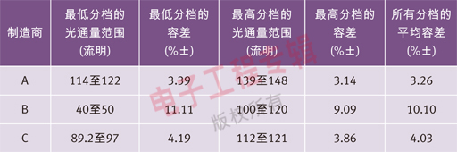
Table 1 Luminous flux binning results for high-end cold white LEDs at the world's top three power optoelectronic semiconductor manufacturers at 350 mA and 25 °C.