Abstract: In order to realize a simple and reliable embedded video surveillance system, based on Samsung S3C6410 microprocessor system, combined with embedded technology and image processing technology, S3C64 10 hardware coding module MFC is used for MPEG-4 encoding. The real-time transport protocol performs video transmission over the network. Tested under the condition of local area network, the system collects and transmits video with good quality and stable performance, and meets the requirements of low-cost and high-reliability embedded video surveillance. While describing the system framework, the key code examples of the implementation part are more specifically explained.
Keywords: video surveillance; S3C6410; MPEG-4; real-time transport protocol
The field of application of video surveillance is increasingly widespread. With the rapid development of electronic information technology, multimedia technology and network technology, embedded video surveillance technology has also developed rapidly. Compared with traditional monitoring systems, embedded monitoring systems have the characteristics of low cost, small size, flexibility and high reliability. This paper implements a simple and efficient video surveillance system based on Samsung S3C6410 microprocessor based processor ARM11. The system can use either a network cable for transmission or a wireless USB network card for wireless transmission. While explaining the system framework, this paper focuses on the specific software implemented by the system.
1 System composition and working principle The embedded video monitoring system consists of hardware and software. The hardware part is composed of a video acquisition module, a video coding module, a network transmission module and an embedded processor module; the software part is based on an embedded operating system platform, including a video data acquisition module, a video coding module and a network transmission module.
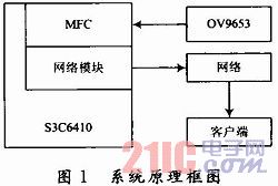
The overall design principle of the system is: the video data is collected by the OV9653's 1.3 megapixel camera, and then the video data is sent to the MFC (Multimedia Format Codec) module of the S3C6410 for video encoding, and then the MPEG-4 video stream is obtained, and finally the data is passed. The network module sends to the receiving end. The block diagram of the system is shown in Figure 1.
This article refers to the address: http://
2 system hardware design
2.1 Data Acquisition Module The video acquisition module uses the OV9653 camera sensor. The OV9653 camera sensor is a low voltage CMOS image sensor. The output format of the captured image can be YUV/YCbCr
4:2:2 or RGB 4:2:2.
2.2 Video Encoding Module The system is based on the ARMSYS6410 development board. The ARMSYS6410 development board is based on the Samsung S3C6410 microprocessor (ARM1176JZF-S core).
The MFC (Multimedia Format Codec) module provided by the S3C6410 is used for encoding, and the YUV format data collected by the OV9653 is encoded into an MPEG-4 format data stream. At the same time, the RGB format data collected by the OV9653 can also be directly displayed on the LCD screen.
2.3 Network Transmission Module The ARMSYS6410 development board based on S3C6410 microprocessor provides 1 channel 10M/100M network interface, 1 channel USB2.0-OTG, 1 channel USB Host. In the network transmission module, the network interface can be directly used for wired network data transmission, or the network interface of the USB interface can be used for wireless data transmission. The difference is that the drivers used in the software section are different and have no effect on the structure of the program.
2.4 Embedded Processor Module The Samsung S3C6410 microprocessor (ARM1176JZF-S core) is a high-performance multimedia application processor with a powerful hardware multimedia format codec unit (MFC), complete external equipment, and Operating frequency up to 667 MHz.
3 system software design Embedded operating system is an important part of embedded system, providing a software platform for application development. Due to the good tailorability and portability of Linux systems, Linux systems are currently being used to develop embedded systems.
Based on the S3C6410 ARMSYS6410 development board, the operating system source code based on the Linux 2.6.28 kernel has been provided. By embedding the various functional modules of the kernel, compiling the image file, and then downloading it to the development board, the Linux embedded operating system and the corresponding driver can be transplanted.
The overall data flow of the system is shown in Figure 2. Figure 1 shows the raw data from the external camera to the camera driver module. 2 indicates that the data is transferred to the memory by the driver module. The data can now be in a different format. 3 indicates that the data is transferred from the memory to the input buffer of the video encoding module. 4 indicates that the MFC encoding module reads data from the input buffer for MPEG-4 encoding. 5 indicates that the data is transferred to the output buffer of the video encoding module after the encoding is completed. 6 indicates that the encoded data is read from the output buffer of the video encoding and transmitted to the network transmission module for transmission.
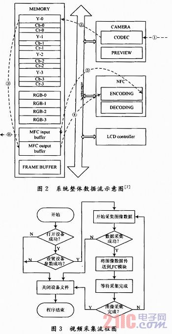
It should be noted here that the video input buffer in the illustration is an input buffer for the decoding module, but an output buffer for the encoding module. The same is true for the output buffer in the illustration.
3.1 Video Data Acquisition Program The video capture program uses memory maps for reading. The device map is directly mapped into the memory through the memory map, bypassing the kernel buffer, and the process accessing the device file is the same as accessing the normal memory, which greatly improves the reading speed of the video data.
The flow chart of the video capture part is shown in Figure 3.
The key codes in the video capture section are listed below.
First open the device, where CODEC_NODE is a predefined macro that represents the path to the camera node file.
Dev_fp=open(CODEC_NODE, O_RDWR);
In the Set Parameters section, you first need to get the device capability parameters, check if you have the required features, and then set the parameters. Use the code below to implement.
Ioctl(dev_fp,VIDIOC_QUERYCAP,&cap);
The previous line of code gets the device's function information and stores it in the parameter caF. After checking that the device has the required functionality, the next line of code is parameterized.
Ioctl(dev_fp,VIE)IOC_S_FMT,&codec_fmt);
Where codec_fmt is a structure type parameter of a format information.
On the Linux platform, the acquisition of image data is implemented in a similar way to file reading, using the following code.
Read(dev_fp,g_yuv,YUV_FR_BUF_SIZE);
The data is transferred to the MFC module, which can directly share the buffer, which reduces the transmission of data in memory and increases efficiency.
Finally, close the device file. Stop image acquisition first, then close the file.
Ioctl(dev_fp,VIDIOC_STREAMOFF,&start);
Close(dev_fp);
The above code snippet is the key code segment of the video capture part. There are a lot of control flow and other control flow parts in the implementation part, which are not described in detail here.
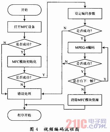
3.2 Video Encoding Program The video encoding part directly uses the S3C6410 MFC video codec module for video encoding. Due to the hardware coding, the coding efficiency is very high. At the same time, in the design of the program, there is no need to involve specific hardware details, only the driver module provided by S3C6410. The flow chart of the coding part is shown in Figure 4.
The key codes for the video encoding section are listed below.
hOpen=open(MFC_DEV_NAME, O_RDWR | O_NDELAY);
The previous line of code opens the MFC device. The MFC device file path is specified by the predefined macro MFC_DEV_NAME.
The initialization part of the module needs to specify the length and width of the encoded frame, the rate of the encoded frame, and so on. The initialization information is not directly applied to the device, but is stored in the structure type parameter pCTX of an encoding parameter, and then the parameter is set with the following code, that is, the parameter is applied to the actual device.
Ioctl(pCTX->hOpen, cmd_init, &mfc_args);
The encoding part is implemented with the next line of code.
Ioetl(pCTX->hOpen, cmd_exe, &mfc_args);
After the encoding is completed, the memory address of the encoded video frame can be obtained by a function. The function prototype is:
Void*SsbSipMPEG4EncodeGetOutBuf(vold*openHandle, long*size).
Finally, close the device file.
Close(pCTX->hOpen);
Similarly, for some of the flow control part of the code, limited space, there is no detailed description.
3.3 Network transmission program The network part uses the RTP real-time transmission protocol to transmit video data. RTP (Real-time Transport Protocol) is a transmission protocol used for network multimedia data streams. In order to make the implementation of the system simpler and more stable, the existing RTP library is used for program development. This system uses the open source C language library oRTP for development.
The oRTP library is an implementation of the RTP protocol, written entirely in C. The oRTP library implements the RTP protocol using an easy-to-use interface and can work on multiple platforms such as Linux and Windows.
The process of the system network transmission module is relatively simple. The module first initializes the oRTP library, then transfers the data, releasing the oRTP library resources after the transfer is complete. Since the module flow is relatively simple, the flow chart of the system is not listed here, and only the specific implementation is explained. The key codes for the network transport module are listed below. Before the data is transferred, some basic initialization operations are performed on the oRTP library. First initialize the timestamp, using the following line of code.
m_nUser-Timestamp=0;
Then, call the initialization interface function provided by the oRTP library:
Ortp_init();
Ortp_scheduler_init();
After completing the basic initialization, create a new rtp session object and set some parameters and properties of the session object.
Session=rtp_session_new(RTP_SESSION_SENDONLY);
The above code creates a new rtp session object, and then uses the following function to set the parameters and properties of the session.
Rtp_session_set_scheduling_mode(); rtp_session_set_blocking_mode(); rtp_session_set_remote_addr(); rtp_session_set _payload_type();
The above function sets the scheduling management, blocking mode, sending destination address, and payload type of the rtp session object in turn. Due to space limitations, the call parameters are omitted.
Send data to call the library function:
Rtp_session_send_wlth_ts();
After the data is sent, the rtp session object is destroyed, and then the resources of the oRTP library are released.
Rtp_session_destroy(session);
Ortp_exit();
It should be noted in the network transmission module that since the RTP protocol has a limitation on the size of the data packet, if the transmitted video frame is too large, packet transmission processing is required.
4 Conclusion In this paper, based on the S3C6410 microprocessor-based development platform, a video surveillance system based on MPEG-4 encoding is implemented. The S3C6410 integrated MFC module is used for video coding, which achieves high coding efficiency. Finally, network data transmission is performed through the RTP protocol. With a modular design, the network data transmission part of the system is independent of the specific wired or wireless transmission mode. Based on the description of each part of the implementation process, the article describes the key part of the code implementation in detail. In the experimental test, the data encoding efficiency is very high. Adopted
In the MPEG-4 encoding mode, under normal network conditions, the transmission video quality is good and the system runs stably. The experiment confirmed that the system is more feasible.
Bluetooth Earbuds Charging case will recharge your both earbuds at the same time With a dedicated charge storage case, you can charge your earbuds whenever and wherever, it also is very mini that you could take it in your bag! There are also comes with a charge cable for two earbuds charging when you at home.
Bluetooth Earbuds Conveniently with our Built-in Microphone on earbuds with CSR chip. Noise Cancellation for safe and sound One-Touch Hands-free Calling so you don't have to stop biking, running, walking, or driving. Ould be connected as a pair or used each separately. Glad to share one for your friend or your family. Music sharing with true free wireless bluetooth.
Bluetooth Earbuds
Bluetooth Earbuds,Wireless Earbuds,Mini Wireless Earbuds,Wireless Bluetooth Earbuds
ShenDaDian(China) Digital Electronics Co.,Ltd , http://www.btearbuds.com