I. Introduction
The processing object of the 3D chip is an object represented by a polygon. There are two advantages to representing an object with a polygon: first, directly (although cumbersome), the piecewise linear feature of the surface represented by the polygon can be eliminated by the shading technique except for the contour; secondly, the geometric information of only the vertices of the polygon is stored. The information required for the calculation of the light and dark color of each pixel inside the polygon is interpolated from these vertex information, which is a fast shading technique that is easily supported by graphics hardware. Graphics hardware that supports polygon rendering can also draw objects represented by bicubic surface patches. This can be done by triangulating the surface of the object and replacing the surface representation of the original object with an approximated triangular mesh. Of course, representing objects with polygons has its drawbacks. For example, the difficulty of texture mapping and shadow generation is increased. The number of triangles needed to represent complex objects in detail will become very large.
Displaying the object represented by the polygon on the computer screen, the process involves the representation of the object inside the computer, that is, the data structure of the object, the organization structure of the scene composed of the object, and a series of transformations of the object from the scene to the screen space. And a series of rasterization processes to produce the final screen image. These aspects all involve specific processing algorithms, and the corresponding algorithms have many different variants. The following is a brief analysis of the graphics processing and related algorithms involved in 3D chips. These are the basis for understanding 3D graphics processing and graphics hardware.
Second, the representation of 3D objects
The surface of an object with a complex shape can be approximated by a polygonal patch. Taking the cylinder of Fig. 1 as an example, the cylinder surface can be approximated by 2N triangles, and the two ends can be approximated by two N-sided shapes. The piecewise linear feature of the polygon model on its contour is the main visual defect of this representation. The only way to improve is to increase the resolution of the polygon. For a complex shape, in order to fully represent its details, more than 100,000 polygons are often used. This will consume a lot of database access time and drawing time. When the polygon model is enlarged, a connection problem occurs. This is the so-called "geometric aliasing." The polygon representation of the object can be either manually extracted by interactive design or by a laser scanning device. In summary, objects represented by polygons are not particularly suitable for interworking or for free shape changes. It is difficult to ensure that the integrity of the polygon representation is maintained when changing the shape of the object.
The information needed to color the polygons is stored in a hierarchical data structure. Each object surface is defined by a pointer to a polygon table containing a set of polygons approximating the surface, each polygon being pointed to by a vertex table. The pointer definition, the vertex table contains all the vertices of each polygon. Specifically, you need to store the following information for each polygon:
1) The vertex table of the polygon, each vertex is a three-dimensional coordinate defined in the local coordinate system when the object is created.
2) The normal vector table of the vertices, which is the information required by the shading algorithm. The vector is represented by three components in the same local coordinate system.
3) The normal vector of the polygon, which is the true geometric normal vector of the plane containing the polygon. This is the information needed for the back delete operation.
The traditional way to draw a polygonal object is to treat the polygon as a separate drawing entity so that the shared edges between the polygons are processed twice. To avoid this, an edge-based rendering method can be used, in which case the representation of the polygon is based on the edge of the polygon rather than the polygon itself. The edge-based approach means that the organization of the rendering process uses a scanline-based algorithm, and the scanline-based algorithm will simultaneously process all polygons that intersect the current scanline. At this point, the maximum number of polygons that can be stored in the memory that can be processed simultaneously becomes the upper limit of the complexity of the scene that can be drawn. This problem can be solved by using a full-screen Z-buffer and confining the scan line algorithm to the polygons contained in the object.
ONEREEL supply kinds of empty 3D printer filament spools/3D Printer Spool/3D Empty Spool for metal 3D Printer, Large 3D Printer, Industrial 3D Printer, Desktop 3D Printer, Professional 3D printers, FDM 3D printer and DIY 3D Printer.
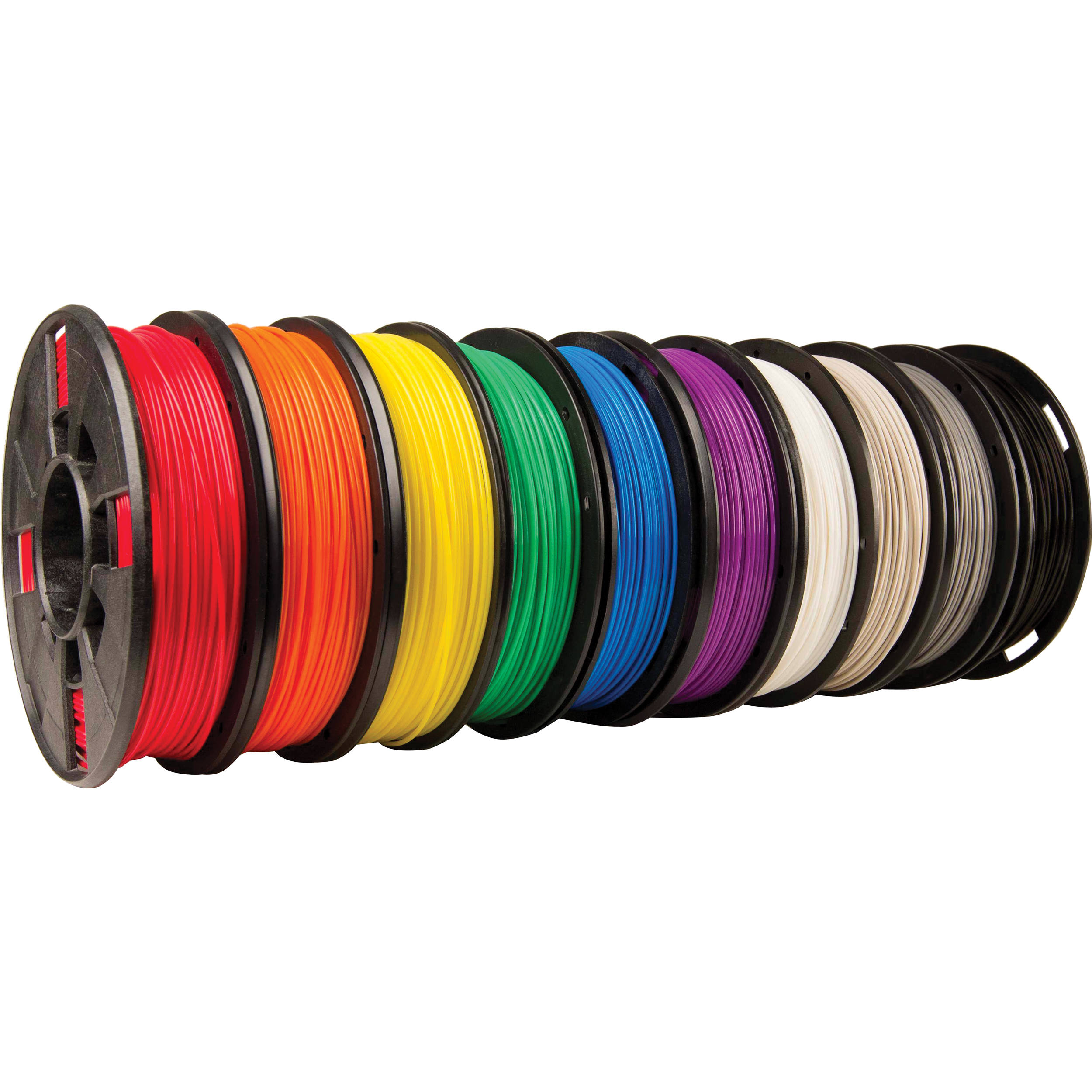
1.3 KG / Roll 1.75mm ABS Filament for FDM 3d printers
Colorful Rapid Phototyping 3D printer plastic filament with HIPS/PLA/ABS material.
We can also make the empty 3d spools under OEM requirement.

empty 3D Printer spools, Large 3D Printer Spools, Desktop 3D Printer Spools,3D Printer Spool,3D Empty Spool
NINGBO BEILUN TIAOYUE MACHINE CO., LTD. , https://www.spool-manufacturer.com