Abstract Aiming at the violation behavior of vehicle pressure line, a computer vision based vehicle pressure line detection method was proposed. Firstly, the Hough transform is used to automatically extract the yellow line in the traffic video image. Then the foreground vehicle is extracted from the image by the background difference method, and the vehicle is segmented by the Otsu method to obtain the vehicle position. Finally, according to the yellow line area and the vehicle area, There is overlap to determine if the vehicle is pressing. The experimental results show that the method can meet the requirements of accurate and efficient.
Key words image processing; line extraction; vehicle detection
With the rapid development of the transportation industry, the number of vehicles has increased sharply, and various vehicle violations have emerged in an endless stream. Vehicle yellow lines are a serious traffic violation. It is of practical value to use video to detect vehicle yellow lines. Aiming at this problem, this paper proposes a computer vision based vehicle pressure line detection method.
1 Vehicle yellow line detection algorithm
1.1 Image Preprocessing Image preprocessing is the first step in video image processing. It is the process of filtering the input image to remove noise and enhance the image. After the grayscale, binarization and median filtering of the image, the visualization effect of the region of interest can be improved, which is beneficial to further processing of the image.
1.2 Edge detection The basic idea of ​​edge detection is to use the edge enhancement operator to highlight the local edges in the image, then define the "edge strength" of the pixel, and extract the edge point set by setting the threshold. Commonly used detection operators are Roberts operator, Sobel operator, Canny operator, and Laplacian operator. After experimental comparison, it is found that the edge extraction effect using Canny operator is better than other operators, so the Canny operator is used in the yellow line extraction.
1.3 Straight line extraction To determine whether the vehicle is pressing the line, the position of the yellow line must be determined in advance. In this paper, the Hough transform is used to extract the line, that is, the position of the line is automatically obtained through the image information.
Hough transform is a common method of directly detecting the target contour and connecting the edge pixels of the image by using the global characteristics of the image. Under the condition that the shape of the region is known in advance, the boundary curve can be conveniently obtained by Hough transform to connect the discontinuous edge pixels. The basic idea of ​​Hough transform is to use the duality of points and lines. The image is transformed in the image space before the transformation, and is transformed into the parameter space. In the image space XY, all straight lines passing through the point (x, y) must satisfy the equation y=px+q (1)
Where p is the slope and q is the intercept. If x, y is treated as a parameter, it represents a straight line passing through the point (p, q) in the parameter space PQ. Each point on the line passing through points (xi, yi) and (xj, yj) in image XY corresponds to each line in the parameter space, and these lines intersect at (P', q'), (p', q ') happens to be the parameter of the line passing the points (xi, yi) and (xj, yj) in the image XY. It can be seen that the points on the same line in the image space correspond to the intersecting lines in the parameter space. When some edge points in the image space are given, the line equations connecting the points can be determined by Hough transform.
1.4 Commonly used moving target extraction algorithms for vehicle extraction include inter-frame difference method, background difference method, background model method and many improved algorithms based on these basic algorithms. Among them, the background difference method is mainly applied to the fixed camera, the background image is relatively static, the image is selected as the background image, and the difference between the current image and the background image is calculated to realize the detection of the moving target R(i,j)=|F (i,j)-G(i,j)| (2)
Where R(i,j) is the moving target to be tested; F(i,j) is the video sequence image; G(i,j) is the background image.
Based on the fixed road traffic video, the paper satisfies the conditions of using the background difference method. Therefore, the background difference method is used to extract the target vehicle. The advantage of the background difference method is that the position is accurate and the calculation speed is fast. The disadvantage is that it is sensitive to changes in ambient light. In an uncontrolled environment, it is necessary to add a background image for updating. At present, the main background update algorithms include image sequence averaging method, IIR filter method and so on.
1.5 The vehicle is marked to more clearly indicate the position of the vehicle, and the vehicle area is marked with a rectangular frame. The image segmentation technique is first used to segment the vehicle from the image. The image segmentation is defined as: the set R represents the entire image region, and the segmentation of R can be regarded as dividing R into N non-empty subsets R1, R2, ..., RN satisfying the following conditions. 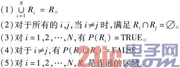
Where P is the logical predicate for the elements in all sets Ri, and Ф represents the empty set. The Dajin method is used as the threshold segmentation method. Otsu (Ostu) was proposed by Otsu in 1979. For image I, T is the segmentation threshold of foreground and background. The number of front spots accounts for w0, the average gray is u0; the number of background points accounts for w1, the average gray The degree is u1. The total average gray level of the image is uT = w0 × u0 + w1 × u1. T is traversed from the minimum gray value to the maximum gray value. When T makes the variance value σ2 = w0 × (u0 - uT) 2 + w1 × (u1 - uT) 2 maximum, T is the optimal threshold for the division. Variance is a measure of the uniformity of gray distribution. The larger the variance value, the larger the difference between the two parts of the image. When part of the foreground is divided into the background or part of the background is divided into the foreground, the difference between the two parts will be smaller. Therefore, the segmentation that maximizes the variance means that the probability of misclassification is minimal. The amount of calculation directly by the Otsu method is large, so the equivalent formula σ2=w0×w1×(u0-u1)2 is used in the implementation. After the vehicle is divided, the image morphology processing is performed to complete the rectangular frame marking.
2 Experimental results and analysis A section of urban road traffic video obtained by a fixed camera was selected as the research object. Firstly, the image segmentation technique is adopted, and only the approximate area near the yellow line is selected to obtain the detection band, thereby reducing the amount of data and improving the processing speed. In actual situations, due to the influence of light and the deviation of the artificially defined yellow line, the yellow line in the image may not necessarily be a straight line in a strict sense. When the yellow line is calibrated with the Hough transform, the situation shown on the right side of Figure 1 is caused: the two yellow lines are not complete straight lines, but are connected by straight line segments. You can get two yellow lines in the road by connecting the endpoints that are furthest away. After the Hough transform, you can get the endpoints of all the segments, that is, the endpoints marked with a cross. Then use Matlab to calibrate the position of the yellow line in the figure, as shown in Figure 1.
This article refers to the address: http://
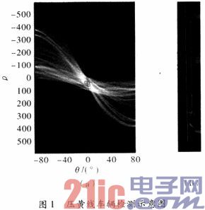
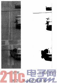
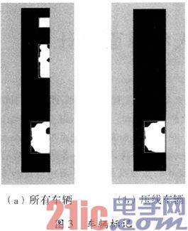
The two straight lines in Figure 1(b) are the yellow lines calibrated by the above method. After the yellow line is calibrated, the yellow line area is between the two. By judging whether there is a vehicle in this area, it can be judged whether there is a vehicle pressure line to achieve the detection purpose. It can be seen from the figure that there is a behavior of the vehicle having a yellow line. After determining the position of the yellow line, the position of the vehicle needs to be marked with a rectangular frame in the figure. Figure 2 shows the result of the vehicle segmentation, and Figure 3 shows the result of the process.
(1) The main control unit. It is the core component of the vehicle terminal. It is mainly responsible for communication with the Beidou positioning navigation block and the GPRS module, providing an interface LED display and touch screen for human-computer interaction, and supporting the underlying hardware resources and related hardware components required by the embedded operating system.
(2) Beidou positioning navigation module. It mainly receives navigation information of Beidou and provides information such as the position, speed and time of the vehicle in real time.
(3) GPRS touch block. It is mainly responsible for communication with the monitoring center, and transmits the location information, delivery status and security status of the materials to the monitoring center. The commands sent by the monitoring center are also transmitted through the GPRS network.
(4) LED display and touch screen. It mainly provides a platform for interpersonal interaction, and provides a simple and friendly interface through the LED display screen; the user can input control commands through the touch screen.
4 Conclusion Based on the “Beidou No. 2†material transportation monitoring system, the “Beidou No. 2†satellite positioning navigation system is used for positioning and navigation, and the communication between the monitoring center and the terminal is realized by the GPRS communication network. "Beidou No.2" is a global satellite status system independently developed by China. It is not a simple extension of the function of "Beidou No.1", but a GPS global positioning system and a Galileo system. The positioning accuracy reaches the level of GPS civilian use, and the technology is not subject to people. The GPRS communication network has the advantages of always online, fast login, high-speed transmission, volume-based charging, and low price. The designed material transportation monitoring system has the advantages of accurate positioning, low price, simple and practical, and has broad application space in the field of material transportation monitoring.
PZT Piezoelectric Cylinders/Tubes
Yuhai company develop and produce of various tube/cylinder sizes, bearing variety of electrode and metallisation configurations. The tubes is fabricated from various published and additional custom in-house Piezoelectric Material formulations for applications such as high power, sensitivity, stability needs.
Features
- · Choice of metallisation (Silver, Nickel, Gold and others on request)
- · Evaporated and chemically deposited metallisation's available
- · Thickness/Radial frequency tuning available on request
- · Wrap around electrode configuration
- · Wide choice of PZT formulations
aApplications include
- · Hydrophones
- · Fibre optic stretcher
- · Augmented reality
- · Torpedo decoys
- · Accelerometers
- · Pressure sensors
- · Print head transducers
- · Oil and gas exploration
- · Scientific equipment
Tubes
Height:
1-100mm
OD:
6-180mm
ID:
5-150mm
Wall: 0.5-15mm
Piezo Tube,Piezoelectric Tube,Piezo Electric Tube,Piezo Ceramic Tubes
Zibo Yuhai Electronic Ceramic Co., Ltd. , https://www.yhpiezo.com