I studied the battery repair instrument and shared some of my experience. I hope that you will be enlightened. . . 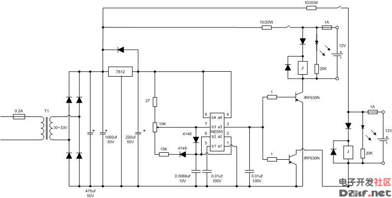
As shown above, this is a circuit diagram of the existing product, the original design can be found in the book of ZTX teacher. . .
The working principle of my analysis: 220V AC transformer to 30V or so, after bridge rectifier filtering, one channel is supplied with 7812 regulated output to drive 555 time base circuit composed of duty cycle adjustable multi-harmonic oscillator, output rectangular square wave drive two The circuit electronic switch IRF630N forms a pulse charging of the charged battery. Relays and diodes form an anti-reverse protection.
The original design and the current product comparison: the original design has two levels of 7824, 7812 voltage regulator, each output has LM317 constant current, the current product greatly simplifies the line, eliminating all unnecessary parts, forming a very concise circuit , enough to meet the demand. The only pity is that the input and output voltage difference of the 7812 is too large and the loss is large. . .
I have improved his research: the current limiting resistor dissipates power and heat is quite powerful, but in order to achieve >30V pulse and reasonable current, there is no way, I simply add a heat sink to the board and solder it to the board. On the back side, the high temperature is jeopardized by electrolytic capacitors. The current product uses a small capacitor to complete the protection of the 7812 input short circuit, I still think it is better to use the diode. . . 7812 output filter capacitor I still make up. . . The LED current limiting resistor is too small, 15-20K is more suitable, but there is still a problem: if the battery is not turned on, the battery will discharge and discharge current is nearly 50mA. . . The LED will remain lit when the battery is disconnected midway. . . If you have a small problem, you don't want to change him anymore. . .
It is recommended that the manufacturer pay attention to the heat dissipation problem, and the current limiting resistor is very hot. . .
Personally think that large-scale application should use pulse generation and pulse power separation, which can ensure that 7812 works under reasonable pressure difference, and can improve power utilization efficiency and avoid unnecessary waste, but should seriously consider line interference and loss. . . There should be no problem with doing more roads on a board. . .
I am only for research and improvement, and for common progress, I hope that everyone will explore more, and others feel that the profit of this product is still too high. . .
Look carefully at the circuit diagram, the three legs of the potentiometer (3296 10K) must be connected, the order direction does not matter. The thing that the United States is jealous of telling the truth, I have not studied it, because I started by looking at the existing mature products at hand. . .
Individuals strongly recommend that the large-scale application separate the pulse generation and the pulse charging. That is to say, the 555 part is separately supplied with a winding of 15V or less, and the loss will be small; and the pulse charging part can make the voltage higher. More than 40V is no problem, the two large capacitors in the latter stage are indeed necessary to add, as long as the board space is reasonably arranged. . . Be sure to pay attention to the current limiting resistor to avoid electrolytic capacitors, etc., otherwise the heat is too horrible, it is best to have active heat dissipation. . .
The pulse output of the 555's 1, 3 feet seems to be about 3V, so I will measure more. . .
The two large electrolytic capacitors output from the latter stage mainly increase the pulse current amplitude and make the rising edge steeper. However, the specific problem is that the pulse current is large and the average current is also increased, so I think the capacitor is still Need to choose carefully, otherwise the heat of the IRF630N is too large, the load on the output part is relatively heavy, and the impact on the life of the battery plate will be relatively large. . . Specifically, I have the opportunity to try it, maybe 100uf or so is almost the same. . .
Resistor is 1/4W in addition to two 20 ohms and 20W. ~~~ The relay is JQC-3F, 12V, and there are many models that can be used instead~~~
If the battery is not turned on, the battery will discharge and discharge current is nearly 50mA. . . The LED will remain lit when the battery is disconnected midway. . . You can solve the problem by adding a diode to the output.
1. In fact, except for the 4148 diode, all of them use IN4007. The large size is not easy to find on the market. This model is very cheap and cost a few cents. . .
2. The relay is mainly to prevent reverse connection. If you have confidence in your habits, you can really remove it and save a lot of board space. . .
3. The two omitted capacitors are connected after the 20W resistor, before the relay, and the other before the IRF630, but I found that two 2200uf electrolysis is indeed. . . Too much tyrants will cause the average output current to skyrocket, and the IRF630 will not be able to withstand dripping and boiling. . . In the end, I used only a 0.47uf CBB capacitor on each side and soldered it on the back of the board. If you redesign the board, you can arrange it well. . .
4. Adjust the potentiometer to adjust the duty cycle of the output to control the average output current. Generally, it is controlled between 100-200mA. It is not good for the battery, and the effect is too weak and time consuming. . .
The adjustment potentiometer is a 10K type 3296 potentiometer. 5. It is strongly recommended to pay attention to the heat of the current limiting resistor. . . I have added a small radiator to the IRF630. . .
6. The input is best controlled at 30V. I use the ready-made 15V+15V ring cow. The input voltage should not be too high. This circuit design has 30 V after rectification, and the 7812 will be higher. No, the heat sink of the 7812 should not be too small, and the loss on the top is very large. . .
7. I have now set a 4U 19-inch standard chassis, which is equipped with two 100W ring cows, eight circuit boards are vertically inserted inside, and I have made a temperature control circuit that controls four 12V cooling fans. Two temperature steps are automatically controlled. . .
8 The function of the relay is reversed and protected, and does not affect the charging parameters. 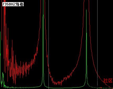
The difference in the pulse current of the improved circuit is very large. If the battery is dehydrated due to excessive assembly, the repair (protection) function is low. The frequency is generally centered on 8.333 KHz. The pulse width is different, the width is larger, the pulse current is relatively smaller; the width is smaller, and the pulse current is larger. However, the pulse width should generally be guaranteed to be more than 12 microseconds. In extreme cases, it should be guaranteed to be more than 6 microseconds. Below 6 microseconds, the ion motion speed can not keep up, the repair (protection) function is reduced, and the three feet are removed. Foot grounding capacitor,
Second, replace the 15k resistor below the adjustable potentiometer with 5k. 
Improved waveform 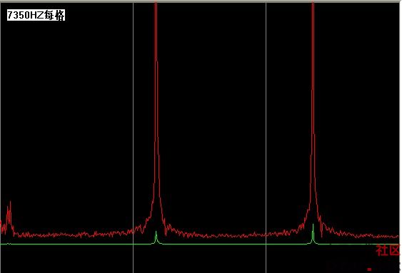
Desulfurization board 
Sewage Gas Generator,Propane Powered Generator,Hydrogen Generator,Gasoline Generator
Jiangsu Vantek Power Machinery Co., Ltd , https://www.vantekgenerator.com