Before the car is delivered from the factory, the R&D design and the whole vehicle are subject to strict inspection to ensure the quality of the products and the reliability and safety of the work of each sub-system. With the development of automotive electronics technology, more and more test projects and testing requirements, the scalability of test systems has received more attention. The new generation of automotive electronic system testing technology focuses on testing the operational status of various electromechanical systems while driving, in order to shorten test time and complete reliability testing. Car testing types vary and involve different signal types. For example, the efficiency of the air conditioning system is verified by temperature measurement of multiple points; the CAN network is monitored to ensure normal communication between the control units or devices; and the ride comfort is verified by acceleration measurements. These different kinds of tests often require corresponding test equipment to complete, which requires engineers to familiarize themselves with these different test equipment.
This article refers to the address: http://
In order to ensure the smooth completion of the test, the test system must have a high degree of reliability. For example, sensor measurement data and image data need to be recorded in a car crash test. Due to the complicated test environment, the common-mode voltage of the stack in the fuel cell test may exceed kV, and good ground isolation performance is required. Taking into account test space, budget and other factors, manufacturers also hope to replace these different discrete test equipment with an integrated and highly reliable test system, in order to define functions according to specific applications, while meeting the test environment and technical requirements.
Field Programmable Gate Array (FPGA) technology features custom logic functions and high reliability. Engineers can integrate FPGA technology into test systems to solve the above-mentioned in-vehicle test difficulties while meeting low cost, system scalability and Complex test environment requirements. This article will explore the application of FPGA related technology in vehicle testing.
FPGA technology - "one platform for multiple applications"
FPGA is the product of the further development of programmable devices such as PAL, GAL, PLD, etc. Its logic function is completed by an internal regular logic cell array (Logic Cell Array). The logic cell array includes three parts: a Configurable Logic Block, an Input Output Block, and an Interconnect. Engineers can reconfigure the logic and I/O modules inside the FPGA through software programming to implement custom logic.
FPGA technology has many advantages, including custom I/O hardware timing and synchronization, high reliability, digital signal processing and analysis. These advantages provide a flexible, low-cost solution for fast-growing automotive electronic test technology.
There are also differences in technical specifications for different in-vehicle tests, including sampling rate, signal conditioning, processing, and analysis. For example, the sampling rate ranges from 15 Hz for GPS data recording to 200 kHz for collision tests. Application FPGAs are directly connected to digital and analog I/O, which can define different sampling rates and triggers for each channel, enabling a single system to solve all in-vehicle test applications and avoid the need for custom hardware or multiple test systems. That is, a single FPGA platform can be used for low-speed, high-precision GPS or temperature recording. It can also be used for collision tests with high sampling rate requirements through fast programming. It is also possible to coexist different sampling rates in the same measurement application in parallel ( For example, a 50 kHz vibration test can be performed while configuring the FPGA to achieve 10 Hz temperature acquisition); synchronization between any I/O can also be achieved (eg, nanosecond synchronization between CAN bus data and digital or analog I/O signals) measuring). Without FPGA technology, it is difficult for a single system to meet these different in-vehicle testing needs at the same time.
Advanced signal processing and analysis of any sensor signal using FPGA technology. In many signal processing systems, the underlying signal preprocessing algorithm has to process a large amount of data, so the processing speed is high and the algorithm is relatively simple. Programming with FPGA can realize the algorithm. At the same time, it can easily perform digital filtering operation, fast Fourier transform (FFT), windowing and other signal processing and analysis on the acquired signals. Sensor-level signal processing and analysis capabilities enable FPGA technology to be successfully applied to the development of high-speed data acquisition processing cards and high-speed image acquisition processing cards.
In addition, FPGA-customizable logic functions are used to develop custom boards for rapid prototyping and hardware-in-the-loop simulation (HIL) of engine control units (ECUs). FPGAs enable extremely fast closed-loop control loop rates at the hardware level. Fast response to CAN, analog or digital signal inputs through FPGA programming, while FPGA parallelism allows multiple fast control loops to be integrated into the same system. For example, Drivven's application of FPGA's reconfigurable performance enables the prototype of the Yamaha YZF-R6 engine control system, eliminating the need to purchase multiple custom hardware during the design process, thereby reducing costs; MicroNova also uses high reliability, The FPGA hardware platform with customizable logic functions enables hardware-in-the-loop simulation of the world's first V12 gasoline engine.
Graphical FPGA programming
FPGA technology has many advantages and can be widely used in automotive testing and development of custom boards. When engineers use FPGA programming, they often need to master knowledge of hardware design languages ​​such as VHDL. Graphical development tools, such as National Instruments' (NI)'s highly efficient graphical development environment, LabVIEW, are designed for engineers and scientists who need to build flexible, scalable test measurement and control applications to meet their needs. Costs meet the needs of the fastest development systems.
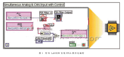
LabVIEW's intuitive graphical development features allow engineers to focus more on feature development than on code writing, dramatically reducing development time and costs. LabVIEW is an open software platform that provides a variety of toolkits and modules for specific applications to enhance and accelerate system development. For example, with the LabVIEW FPGA Module, engineers can create custom hardware by graphically developing custom FPGA logic code and downloading it to the FPGA hardware target on the WINDOWS operating system without the hardware description language and hardware design expertise. As shown in Figure 1, simultaneous measurement of nanoseconds between CAN data and digital or analog signals is performed on the FPGA. When the test requirements change, simply download the new code to the FPGA without having to customize the new hardware. At the same time, the VHDL language interface is provided for the convenience of engineers to directly use off-the-shelf VHDL code. The LabVIEW Real-Time module is used to develop time-deterministic applications for real-time hardware targets; the embedded development system module is suitable for graphical development of any 32-bit processor; the DSP module is suitable for graphical DSP algorithm development, integrated digital filtering The tool design kit; the signal processing toolkit is suitable for high-precision spectrum analysis and display of test data. In summary, the graphical development software LabVIEW greatly enhances the productivity of engineers.
Create high-performance control and acquisition systems using LabVIEW FPGA software and reconfigurable hardware technology. The following two solutions are taken as examples to illustrate the application of hardware platform based on FPGA technology in vehicle testing.
User Solution 1: Portable Vehicle Data Acquisition System
Signal types for on-board data acquisition include temperature signals (thermocouple or RTD), sound and vibration signals (acceleration sensors or microphones with IEPE excitation), pressure and load signals (strain gauges or load cells), position signals (LVDT or linear) Potentiometer), speed signal (encoder), control bus signal (CAN, J1350, ODBII) and video signal. These signals are used to evaluate vehicle performance.
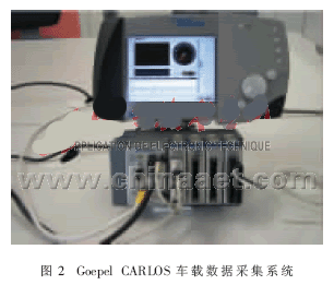
Germany's Goepel Electronic chose NI CompactRIO embedded control system, LabVIEW FPGA module and LabVIEW Real for the needs of portable test equipment with the above signal types, complex environmental conditions, large data storage requirements, in-vehicle test analysis and online diagnostics. The -Time module developed CARLOS (in-car logging system) in a very short time. A low-cost solution using the CompactRIO platform saves money on budget.
The CompactRIO hardware platform shown in Figure 2 is an embedded system based on FPGA technology. The FPGA chip is the core of the CompactRIO architecture and is directly connected to the corresponding in-vehicle module. The on-board module can be directly connected to the vehicle's sensors, actuators and network, and provides signal conditioning, isolation and automotive bus. The platform includes an embedded real-time processor for stand-alone operation, deterministic control, in-vehicle data logging and analysis. CompactRIO has a small, rugged mechanical package that withstands 50 times g shock and operates over the -40 °C to +70 °C temperature range. It provides dual voltage input (9 to 35 V) and can be powered directly from the onboard battery. These make CARLOS suitable for complex in-vehicle test environments and limited test space.
The system has been successfully used for automotive testing in laboratories, wind tunnels and test sites, allowing long-term data logging. In addition, different test requirements can be achieved by selecting the appropriate onboard module and built-in application. For example, in order to evaluate the engine thermal management system in the winter or summer test, it is only necessary to select the vehicle module corresponding to the temperature and other signals and the developed LabVIEW application. At the same time, the program provides alarms, uses the LabVIEW Report Generation Toolkit to write data into the EXCEL form, or directly writes into the database, historical data view and other functions. In addition, the FPGA-based CompcatRIO open architecture allows users to extend the system or further develop custom test systems.
User Solution 2: Custom Remote Module Development
Wireless communication technology has been widely used to achieve state monitoring, precise positioning and remote communication in vehicle travel, including GPS navigation and precise positioning, tire pressure monitoring and the like. Among them, the installation popularity of GPS in Japan and Europe and the United States has increased year by year, and it has received more and more attention in China.
In order to put the product on the market as soon as possible, SEADatentechnik GmbH of Germany chose the CompactRIO open hardware platform and LabVIEW development environment based on FPGA technology. According to the application requirements of vehicle remote control, data acquisition, location tracking, etc., cRIO GPRS (General Packet Radio Service), cRIO GPS (Global Positioning System), cRIO RCC (Radio Controlled Clock) and a hybrid module cRIO Gxxx have been developed, as shown in Figure 3. Show. In the end, the development time of the entire project was 40% shorter than originally planned.
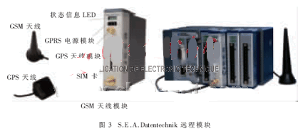
The GPS module achieves precise positioning by receiving GPS signals from the L1 band. The receiver can convert the data to the NMEA 0183 format after startup for further analysis. The backup battery can guarantee the memory function of the receiver and store historical information such as location data. This module can be used for car navigation and precise positioning. The GPRS module transmits measurement data and event messages through the GSM/GPRS public network, and simultaneously uses the SIM card reader to access the GSM/GPRS network, and sends and receives data by SMS. The car anti-theft system can be applied. The RCC module is used for time synchronization of distributed systems; the hybrid module combines the above functions. The high reliability of the CompactRIO embedded system is fully reflected in automotive applications.
In addition to in-vehicle testing, these modules are also widely used in ATM terminals, industrial and telemedicine systems, remote diagnostics, and more.
FPGA technology brings innovation in in-vehicle test technology, and the development of a single system based on FPGA hardware enables different in-vehicle test applications without the need to customize multiple test equipment. Graphical FPGA programming further reduces development time. NI CompactRIO is one of the FPGA-based hardware platforms. Users can develop in-vehicle test applications for automotive buses, different signal types, and even customize their own modules to implement specific in-vehicle test functions.
Radio Fence,E-Dog Fence,Wireless Invisible Fence,Above Ground Electric Dog Fence
Elite-tek Electronics Ltd , https://www.aetertek.ca