In electronic circuits, power, amplification, oscillation, and modulation circuits are called analog electronic circuits because they process and process continuously varying analog signals. A digital electronic circuit of another major class of circuits in electronic circuits. The object it processes and processes is a digital signal that does not change continuously. Digital electronic circuits can be further divided into pulse circuits and digital logic circuits, which process discontinuous pulse signals. A pulse circuit is a circuit that is specifically designed to generate electrical pulses and to amplify, transform, and shape electrical pulses. Pulse circuits are used in timers, alarms, electronic switches, electronic watches, electronic toys, and electronic medical devices in household appliances.
Electrical pulses have a wide variety of shapes, including rectangles, triangles, zigzags, bells, steps, and pointed shapes, the most representative being rectangular pulses. To illustrate the characteristics of a rectangular pulse can be expressed by the pulse amplitude Um, the pulse period T or frequency f, the pulse leading edge tr, the pulse trailing edge tf, and the pulse width tk. If the width of a pulse is tk = 1 / 2T, it is a square wave.
The biggest difference between the pulse circuit and the amplified oscillation circuit, or the characteristics of the pulse circuit is that the transistor in the pulse circuit is operating in the switching state. In most cases, the transistor operates in the saturation or cut-off region of the characteristic curve, so the pulse circuit is sometimes called a switching circuit. It can also be seen from the transistors used that dedicated switching transistors, such as 2AK, 2CK, DK, and 3AK, are used at higher operating frequencies, and general transistors are used only when the operating frequency is low.
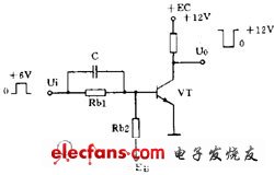
Taking the most commonly used inverter circuit in the pulse circuit (Fig. 1), it is similar to the common emitter circuit in the amplifier circuit in terms of circuit form. In the amplifying circuit, the base resistor R b2 is connected to the positive power source to obtain the base bias voltage; in this circuit, in order to ensure that the circuit is reliably turned off, R b2 is connected to a negative power supply, and R b1 and The value of R b2 is calculated as the requirement that the transistor can reliably enter the saturation or stop region. Not only that, in order to make the transistor Switch faster, an accelerating capacitor C is added to the base, and a positive spike at the leading edge of the pulse causes the transistor to quickly turn on and saturate; a negative spike is generated at the trailing edge of the pulse. The transistor quickly enters the off state. In addition to the emitter output is a special case, the transistors in the pulse circuit are all in the switching state, which is a feature.
Another characteristic of the pulse circuit is that there must be a capacitor (with less inductance) as a key component. Pulse generation and waveform conversion are inseparable from the charge and discharge of the capacitor.
FBELE Speaker (FBELE Loudspeaker) is researching, developing and manufacturing leading edge solutions to enhance the user experience of smart mobile devices. FBELE`s product lines can be found in smartphones and portable electronic devices across the world. FBELE is investing in research and manufacturing to power future smart devices, and bring optimized high performance of smartphone solutions to a wide range of connected devices.
loudspeaker export to worldwide country including Brazil,U.S,Euorpe.etc.
Loudspeaker
Professional Loudspeaker,Small Loudspeaker,Media Loudspeaker,Audio Loudspeaker
Ningbo Best Group Co.,Ltd , http://www.speakerbuzzer.com