Perfect PLC program needs to be written - Database & Sql Blog Articles
The input circuits of various PLCs are generally similar, and there are usually three main types: DC 12–24V input, AC 100–120V or 200–240V input, and a third type that supports both AC and DC. External input devices can be either passive contacts or active sensors, and they must be connected to the PLC through its terminal block. To ensure proper operation, a closed circuit must be formed, which means a power supply is necessary.
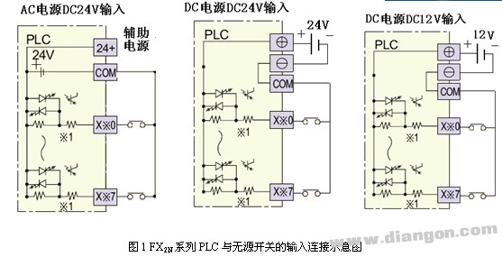
1. Passive Switch Wiring: The FX2N series PLC only supports DC inputs. Inside the PLC, the input terminal is connected to the internal 24V positive supply, while the COM terminal is connected to the negative side. This setup allows passive switches to operate without an external power source, which is different from many other PLC models. Always check the manual for other PLCs to avoid confusion during installation.
2. Proximity Switch Wiring: Proximity switches require an external power supply to function and output a signal with a certain voltage or current. These sensors come in different configurations based on their working principle, but they are typically categorized as two-wire, three-wire, or four-wire systems. The four-wire type may offer both normally open and normally closed contacts, though only one is used in most cases. Sometimes the fourth wire is used for sensor diagnostics, which isn’t directly connected to the PLC. For practical purposes, it’s best to follow the three-wire wiring method. Figure 2 shows a typical connection between the PLC and the sensor.
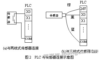
Two-wire systems use a single signal line and a power line, while three-wire systems have separate positive, negative, and signal lines. Different colors are used to distinguish these wires, and color codes can vary depending on the manufacturer. Refer to the device manual for exact definitions. A common example is shown in Figure 2(b), where the black wire represents the signal line, and the white wire is often used for NPN-type sensors. PNP-type sensors will require a different wiring configuration, so always consult the relevant documentation before connecting.
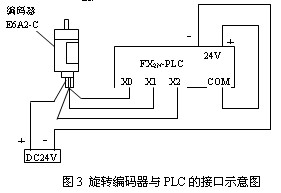
3. Rotary Encoder Wiring: Rotary encoders generate high-speed pulse signals and are widely used in CNC machines and industrial automation systems. The output frequency and phase vary depending on the encoder type—some produce A, B, and C-phase pulses, others only A and B, and some just A. The frequencies can range from 100 Hz to 2 kHz or higher. If the frequency is too high, the standard PLC input may not respond properly. In such cases, the encoder should be connected to a specialized high-speed counting module. For example, the FX2N-11HC module is used with the FX2N-11C model to interface with OMRON E6A2-C series encoders. Figure 3 illustrates the connection diagram.
Refurbished Gaming Laptops,Refurbished Laptops Under $100,Used Gaming Laptops For Sale,Second Hand Gaming Laptop
Guangzhou Panda Electronic Technology Co., LTD , https://www.panda-3c.com