Connection diagram and method of Mitsubishi PLC input circuit - News - Global IC Trade Starts Here Free Join
PLC input circuits are generally similar, and there are usually three common types: DC 12–24V input, AC 100–120V or 200–240V input, and a third type that supports both AC and DC. The external input devices can be either passive switches or active sensors. These devices must be connected to the PLC through its terminal, and a closed circuit must be formed for proper operation, which requires power supply.
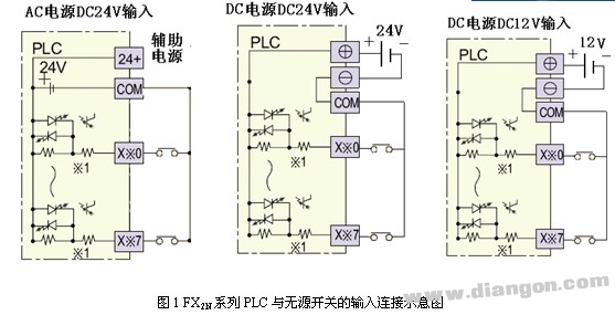
1. Passive Switch Wiring
The FX2N series PLC only supports DC input. Inside the PLC, the input terminal is connected to the internal 24V positive supply, while the COM terminal is connected to the negative side. This means that passive switches don’t need an external power source, which is different from many other PLC models. Always check the manual before using other PLCs to avoid confusion.
2. Proximity Switch Wiring
Proximity switches require their own power supply and output a signal with a specific voltage or current. Depending on their working principle, they can be categorized into two-wire, three-wire, or four-wire types. Four-wire switches may have both a normally open and a normally closed contact, but typically only one is used. In some cases, the fourth wire is used for sensor diagnostics, which is not connected to the PLC input. For practical purposes, it's best to follow the three-wire configuration. Figure 2 shows the typical connection between the PLC and the sensor.
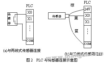
Two-wire switches use one signal line and one power line. Three-wire switches include the positive, negative, and signal lines. Different colors are used to distinguish the functions of each wire, and color definitions vary by manufacturer. Refer to the user manual for accurate information. A common color scheme is shown in Figure 2(b). If the signal wire is black, it’s typically a NPN-type sensor, which is widely used. PNP-type sensors require a different wiring setup and should be handled accordingly.
3. Rotary Encoder Wiring
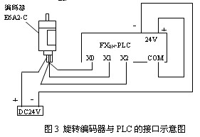
Rotary encoders generate high-speed pulse signals and are commonly used in CNC machines and industrial automation systems. The output frequency and phase vary depending on the encoder type—some provide A, B, C three-phase pulses, while others offer only two or even one phase (like phase A). The frequency can range from 100 Hz to 2 kHz. At lower frequencies, the PLC can easily respond, but at higher speeds, the PLC may not keep up. In such cases, the encoder signal should be connected to a high-speed counting module. For example, the FX2N-11HC module is used with the FX2N-11C model. Figure 3 illustrates the connection between the FX2N PLC and the OMRON E6A2-C series rotary encoder.
Understanding how to properly wire these components ensures reliable operation of your PLC system. Always refer to the manufacturer’s documentation for precise details and safety precautions.
Dell Certified Refurbished,Refurbished Dell Computers,Used Dell Computers,Used Dell Laptops For Sale
Guangzhou Panda Electronic Technology Co., LTD , https://www.panda-3c.com