First, the adjustment of the analog oscilloscope Analog oscilloscope adjustment and use methods are basically the same, the MOS-620/640 dual trace oscilloscope is taken as an example:
1. Introduction of MOS-620/640 Dual Trace Oscilloscope Front Panel The adjustment knobs, switches, buttons and connectors of MOS-620/640 dual trace oscilloscope are located on the front panel, as shown in Figure 6.1.27. The functions are as follows:
(1) Oscilloscope operation part6——“POWERâ€: main power switch and indicator light. When this switch is pressed, the LED indicator 5 on the left side is lit, indicating that the power is on.
2——“INTENâ€: brightness control button. Adjust the brightness of the track or spot.
3 - "FOCUS": Focus adjustment knob. Adjust the focus of the track or highlight point.
4 - "TRACE ROTATION": Track rotation. Adjust the horizontal trajectory parallel to the tick mark. 33 - display. Displays the waveform of the signal.
(2) Vertical axis operation section7, 22 - "VOLTS / DIV": vertical attenuation button. Adjust the vertical deflection sensitivity from 5mV/div to 5V/div for a total of 10 gear positions.
8——“CH1Xâ€: Channel 1 signal is input to the connector. In XY mode, as the X-axis input. 20——“CH2Yâ€: Channel 2 signal is input to the connector. In the XY mode, it is used as the Y-axis input.
9, 21 - "VAR" vertical sensitivity knob: fine-tuning sensitivity is greater than or equal to 1 / 2.5 marked value. In the correction (CAL) position, the sensitivity is corrected to the indicated value.
10, 19 - "AC-GND-DC": Vertical system input coupling switch. Select the coupling mode of the measured signal into the vertical channel. “ACâ€: AC coupling; “DCâ€: DC coupling; “GNDâ€: Ground.

11, 18 - "POSITION": Vertical position adjustment knob. Adjust the vertical position of the displayed waveform on the screen.
12——“ALTâ€/“CHOPâ€: Alternate/intermittent selection button. When double-track display is displayed, release this button (ALT), the signals of channel 1 and channel 2 are alternately displayed, which is suitable for signal waveforms with high observation frequency. ; Press this button (CHOP), the signals of channel 1 and channel 2 are displayed intermittently at the same time, which is suitable for the signal waveform with lower observation frequency. 13, 15 - "DC BAL": CH1, CH2 channel DC balance adjustment knob. When the vertical system input coupling switch is at GND, the vertical attenuation switch is repeatedly rotated between 5mV and 10mV, and the “DC BAL†is adjusted to keep the trace on the zero horizontal line without moving. 14——“VERTICAL MODEâ€: Vertical system working mode switch. CH1: Channel 1 is displayed separately; CH2:
13, 15 - "DC BAL": CH1, CH2 channel DC balance adjustment knob. When the vertical system input coupling switch is at GND, the vertical attenuation switch is repeatedly rotated between 5mV and 10mV, and the “DC BAL†is adjusted to keep the trace on the zero horizontal line without moving.
14——“VERTICAL MODEâ€: Vertical system working mode switch. CH1: Channel 1 is displayed separately; CH2: Channel 2 is displayed separately; DUAL: Both channels are displayed at the same time; ADD: Display the algebra or algebraic difference of channel 1 and channel 2 signals (press the signal reverse key of channel 2 "CH2 INV" Time).
17——“CH2 INVâ€: Channel 2 signal reverse button. Press this button and channel 2 and its trigger signal are reversed at the same time.
(3) Trigger operation part23——“TRIG INâ€: External trigger input terminal. Used to input an external trigger signal. When using this function, the “SOURCE†switch should be set to the EXT position.
24——“SOURCEâ€: Trigger source selection switch. “CH1â€: When the vertical system operation mode switch 14 is set to DUAL or ADD, channel 1 is selected as the internal trigger signal source; “CH2â€: when the vertical system operation mode switch 14 is set to DUAL or ADD, channel 2 is selected. As the internal trigger signal source; "LINE": Select AC power as the trigger source; "EXT": Select the external signal input from the "TRIG IN" terminal as the trigger source.
25——“TRIGGER MODEâ€: Trigger mode selection switch. “AUTOâ€: When there is no trigger signal input, the scan is in free mode; “NORM†(normal): when there is no trigger signal input, the trace is in standby state and not displayed; “TV-V†( TV field): When you want to observe a TV signal; "TV-H" (TV line): When you want to observe a line of TV signals.
26——“SLOPEâ€: Trigger polarity selection button. Released as "+", rising edge triggered; pressed as "-", falling edge triggered.
27——“LEVELâ€: Trigger level adjustment knob. Display a synchronized stable waveform and set the starting point of a waveform. The "+" rotation trigger level moves up, and the "-" rotation trigger level moves down.
28——“TRIG ALTâ€: When the vertical system working mode switch 14 is set to DUAL or ADD, and the trigger source selection switch 24 selects CH1 or CH2, press this button, the oscilloscope will alternately select CH1 and CH2 as internal trigger signals. source.
(4) Horizontal axis operation section29——“TIME/DIVâ€: Horizontal scanning speed knob. The scanning speed is 20 steps from 0.2μs/div to 0.5s/div. When set to the XY position, the oscilloscope can operate in XY mode.
30——“SWP VARâ€: Horizontal scanning fine adjustment knob. Fine-tune the horizontal scan time so that the scan time is corrected to the "TIME/DIV" indication value on the panel. Turn clockwise to the bottom to correct (CAL) position.
31——“×10 MAGâ€: Scan the expansion switch. The scan speed is extended by 10 times when pressed.
32——“POSITIONâ€: Horizontal position control knob. Adjust the horizontal position of the displayed waveform on the screen.
(4) Other operating parts1——“CALâ€: The oscilloscope corrects the signal output. A square wave signal with an amplitude of 2Vpp and a frequency of 1kHz is provided for correcting the compensation capacitor of the 10:1 probe and detecting the vertical and horizontal deflection factors of the oscilloscope.
16——“GNDâ€: The ground terminal of the oscilloscope chassis.
2, the correct adjustment and operation of the dual trace oscilloscope
Correct adjustment and operation of the oscilloscope is important to improve measurement accuracy and extend the life of the instrument.
(1) Focus and brightness adjustment Adjust the focus knob to make the scan line as thin as possible to improve measurement accuracy. The brightness (brightness) of the scanning line should be appropriate. Too bright will not only reduce the life of the oscilloscope, but also affect the focusing characteristics.
(2) Correct selection of trigger source and trigger mode trigger source selection: If the single channel signal is observed, the channel signal should be selected as the trigger source; if two time-related signals are observed simultaneously, the signal period should be selected. The channel acts as a trigger source.
Trigger mode selection: When the measured signal is first observed, the trigger mode should be set to “AUTOâ€. After the stable signal is observed, adjust other settings. Finally, set the trigger mode switch to “NORM†to improve the sensitivity of the trigger. When observing a DC signal or a small signal, the "AUTO" trigger mode must be used.
(3) Correct choice of input coupling
The correct input coupling method is chosen according to the nature of the observed signal. Under normal circumstances, when the observed signal is DC or pulse signal, the "DC" coupling mode should be selected; when the observed signal is AC, the "AC" coupling mode should be selected.
(4) Reasonably adjust the scanning speed Adjust the scanning speed knob to change the number of waveforms displayed on the screen. Increase the scanning speed, display less waveforms; reduce the scanning speed, display more waveforms. The displayed waveform should not be excessive to ensure the accuracy of the time measurement.
(5) Adjustment of waveform position and geometry When observing the signal, the waveform should be at the center of the screen as much as possible to obtain better measurement linearity. Correctly adjust the vertical attenuation knob to make the waveform amplitude more than half as much as possible to improve the accuracy of voltage measurement.
(6) Reasonable operation Dual channel sets the vertical working mode switch to “DUALâ€, and the waveforms of the two channels can be displayed simultaneously. To observe a stable waveform, the display of the waveform can be controlled by the “ALT/CHOP†(alternate/intermittent) switch. Press the “ALT/CHOP†switch (positioned on CHOP), the signals of the two channels are intermittently displayed on the screen. This setting is suitable for signals with high observation frequency; release the “ALT/CHOP†switch (set to ALT) ), the signals of the two channels are alternately displayed on the screen. This setting is suitable for signals with low observation frequency. In dual channel display, the trigger source must also be selected correctly. When the CH1 and CH2 signals are synchronized, select any channel as the trigger source, both waveforms can be displayed stably. When the CH1 and CH2 signals are not correlated in time, press the “TRIG.ALT†(trigger alternate) switch. At each scan cycle, the trigger signal alternates once, so the waveforms of both channels are displayed steadily.
It is worth noting that when dual channel display is used, the “CHOP†and “TRIG ALT†switches cannot be pressed at the same time because the “CHOP†signal becomes the trigger signal and cannot be displayed simultaneously. When using two channels for phase and time comparison measurements, both channels must be triggered with the same sync signal.
(7) Trigger level adjustment
Adjusting the trigger level knob changes the valve level preset by the scan circuit. When rotating in the "+" direction, the valve level moves in the positive direction; when rotating in the "-" direction, the valve level moves in the negative direction; when in the middle position, the valve level is set on the average value of the signal. If the trigger level is too positive or too negative, no scan signal will be generated. Therefore, the trigger level knob should normally remain in the middle position.
Second, the analog oscilloscope measurement example 1, measuring DC voltage(1) Place the oscilloscope vertical sensitivity knob in the calibration position and the trigger mode switch to “AUTOâ€.
(2) Put the vertical system input coupling switch to “GNDâ€, and the vertical position of the scan line is the zero voltage reference line, which is the time base. Adjust the vertical displacement knob to drop the scan line to a suitable horizontal scale line.
(3) Connect the signal under test to the input of the oscilloscope and set the vertical system input coupling switch to “DCâ€. Adjust the vertical attenuation knob to make the scan line have the proper offset.
(4) Determine the measured voltage value. The product of the measured voltage value is the product of the offset of the scan line on the Y axis and the corresponding gear voltage of the vertical attenuation knob.
(5) Determine the polarity of the DC voltage according to the offset direction of the scanning line. When the scan line moves above the zero voltage reference line, the DC voltage is positive, and vice versa.
(6) Connect the signal to be tested to the input terminal of the oscilloscope CH1. The DC signal will be offset, and then adjust the trigger “level†to make the waveform stable, as shown in Figure 6.1.28.

Figure 6.1.28 Measuring DC voltage Figure 6.1.29 Measuring AC voltage
If the Volts/div is 50mV/div and the oscilloscope reads 4div (grid), the calculation method is: 50mV/div×4div=200mVP—P. Of course, if the probe is 10:1, the actual signal value is ×10 is 2VP— P.
2, measuring AC voltage(1) Place the oscilloscope vertical sensitivity knob in the calibration position and the trigger mode switch to “AUTOâ€.
(2) Set the vertical system input coupling switch to “GND†and adjust the vertical displacement knob to make the scan line fall on the horizontal center line.
(3) Input the signal under test and set the input coupling switch to “ACâ€. Adjust the vertical attenuation knob and the horizontal scanning speed knob to make the amplitude and number of the displayed waveform suitable. Select the appropriate trigger source, trigger mode and trigger level to make the waveform display stably.
(4) Determine the peak-to-peak value of the measured voltage. The product of the vertical distance (offset) between the highest and lowest points of the waveform in the Y-axis direction and the corresponding gear voltage of the vertical attenuation knob is the peak-to-peak value of the measured voltage, as shown in Figure 6.1.29.
If the input Volts/div is 1V/div and the oscilloscope reads 5div (grid), the calculation method is 1 V/div×5 div=5VP—P. Of course, if the probe is 10:1, the actual value is 50 VP— P.
3, the measurement cycle(1) Place the horizontal scanning fine adjustment knob in the correction position and make the time baseline fall on the horizontal center scale line.
(2) Input the signal to be measured. Adjust the vertical attenuation knob and horizontal scanning speed knob to make the 1~2 waveform display stably on the screen.
(3) Select the start and end points of the cycle of the measured waveform and move the start point to a vertical scale line for reading.
(4) Determine the period of the signal under test. The product of the horizontal distance between the start point and the end point of the signal waveform in the X-axis direction and the time corresponding to the gear position of the horizontal scanning speed knob is the period of the signal to be measured. When measuring the signal period with an oscilloscope, you can measure the time of one cycle of the signal, or measure the time of n cycles, and divide by the number of cycles n. The latter method produces less error.
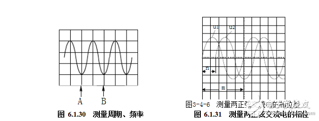
The measurement cycle is shown in Figure 6.1.30. If a cycle is 2 div on the screen and the scan time is 1ms/div, the cycle is: 1ms/div×2 div=2.0ms.
3. Measurement frequency Since the frequency and period of the signal are reciprocal, that is, f=1/T. Therefore, the period of the signal can be measured first, and then the reciprocal can be obtained to obtain the frequency of the signal. As shown in Figure 6.1.30, the period T = 2.0ms, the frequency is 1/2 Hz = 500Hz, if using × 10 expansion, then Time / div is 1/10 of the indicated value.
(1) Place the horizontal scanning fine adjustment knob and the vertical sensitivity knob in the correction position.
(2) Set the vertical system operating mode switch to “DUAL†and make the time bases of both channels fall on the horizontal center scale line.
(3) Input two AC signals with the same frequency but different phases to CH1 and CH2, and set the vertical input coupling switch to “ACâ€.
(4) Adjust the relevant knobs so that two waveforms of moderate size are stably displayed on the screen.
(5) Determine the phase difference between the two measured signals. As shown in Figure 6.1.3, the number of squares occupied by the signal waveform in the X-axis direction is measured by m (5 grids), and then the horizontal grid number n between the corresponding points (such as zero-crossing points) on the two waveforms is measured ( 1.6 grid), then u1 leads the phase difference angle of u2
It is 115.2°.
The measurement of the frequency and phase difference angle can also be performed by the Lissajous graph method, which will not be described here.
Hydraulic High Pressure Sensor
Hydraulic High Pressure Sensor,Thin Film Pressure Sensor,Vacuum Transducer,Brake Fluid Pressure Sensor
Shenzhen Ever-smart Sensor Technology Co., LTD , https://www.fluhandy.com